MIL-PRF-22885H
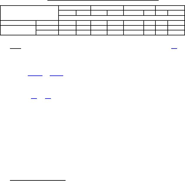
TABLE XV. Temperature conditions during electrical endurance load cycles.
Inductive
Resistive
Lamp
Motor
AC
DC
AC
DC
AC
DC
AC
DC
Percent of electrical load cycles
High temperature
Sea level
100
100
100
100
100
100
Sea level
100
100
Room ambient
temperature
Altitude
100
100
100
100
100
100
4.7.28.2 Loads. Voltage, current, frequency, altitude, and operating cycles shall be as specified (see 3.1).
The loads are as follows:
a.
Resistive load, dc.
b.
Inductive load, dc: Inductive dc loads shall use inductors which have response and stored energy values as
c.
Lamp load, dc: A tungsten lamp, which provides the rated, steady-state lamp current shall be used. The
circuit shall be arranged so as to provide a minimum of 15 seconds cooling time preceding each time a lamp
is energized. Only tungsten lamps having a nominal wattage not to exceed 50 watts, at the voltage
d.
Motor load, dc: The duration of the inrush current shall be not less than .05 second. Only resistive
components shall be used. Switches shall make six times the rated load and break the rated load.
e.
Resistive load, ac.
f.
Inductive load, ac: Inductive ac load test circuits shall consist of inductive and resistive load element
connected in series. The circuit parameters shall be rated inductive load current at 0.7 ±0.05 lagging power
factor at 115 volts.
g.
Lamp load, ac: Similar to 4.7.28.2c above, except that the rated ac voltage shall be used. Only tungsten
lamps having a nominal wattage not to exceed 200 watts, at the voltage specified, shall be used to make up
the load.
h.
Motor load, ac: The duration of the inrush shall be not less than .05 second. Only resistive components
shall be used. Switches shall make six times the rated load and break the rated load.
4.7.28.3 Temperature rise measurement. The switches tested for electrical endurance at the rated resistive
current shall be tested immediately thereafter for temperature rise. The switch terminal temperature shall be
measured using a suitable thermocouple (28 AWG to 32 AWG), while the switch is continuously carrying its
maximum resistive load. The test shall be performed with the switch in still air which has a temperature of 25°C
±5°C. The temperature measuring thermocouple shall be attached to the terminals which were carrying current
during the overload and endurance tests. If wire leads are provided, the measurement shall be made on the copper
conductor at the point of the entrance of the leads to the switch. If wire leads are not provided, the connections to the
switch shall be made with not less than 1 foot length copper wire of the size used during the endurance test and the
measurement shall be made on the terminal at a point adjacent to the insulating medium. The test current shall be
passed through the switch without interruption. The terminal temperature shall be recorded at not less than 5 minute
intervals until the temperature has stabilized or until a minimum period of 2 hours has elapsed. The temperature shall
be considered stable when three successive readings taken at 5 minute intervals indicate no change in temperature.
The ambient temperature shall be measured during the same period at a point sufficiently far from any heat source
(including the test switch) to obtain a representative temperature value for the air reaching the switch by convection.
The temperature rise shall then be calculated by subtracting the lowest recorded ambient temperature from the
highest recorded switch terminal temperature.
31
For Parts Inquires call Parts Hangar, Inc (727) 493-0744
© Copyright 2015 Integrated Publishing, Inc.
A Service Disabled Veteran Owned Small Business