MIL-PRF-22885H
4.7.9.4 Integrated wire terminals. Unless otherwise specified (see 3.1), integrated wire terminals shall be tested as
follows:
a.
Applied force: 15 pounds.
b.
Duration: 5 seconds minimum.
c.
Number of terminals to be tested: Two.
d.
Direction of applied force:
(1)
With the long dimension of the terminal contact vertical, the specified pull shall be applied directly
downward.
(2)
With the long dimension of the terminal contact horizontal, the specified pull shall be applied directly
downward.
e.
A terminal shall be tested only once in one direction.
4.7.10 Strength of actuating means (see 3.15). With the switches mounted by their normal mounting means, a
static load of 25 pounds shall be gradually applied to the pushbutton and maintained for a period of one minute. The
force resulting from application of the static load shall be in a direction to cause actuation of the switch. A circuit,
such as a pilot light, shall be used to monitor for short circuiting during the test.
4.7.11 Strength of actuator (bushing mounted switches, see 3.16). With the switch mounted by its normal means,
a torque of 5 pound-inches in a plane perpendicular to bushing or actuator and about the centerline of the actuator
shall be applied to the actuator for a period of one minute.
4.7.12 Strength of mounting bushing (applicable to threaded mounted bushings) (see 3.17). Switches shall be
mounted on a metal panel by their normal mounting means with the hardware specified. A torque of 15 pound-inches
shall be applied to the mounting nut for 5 seconds maximum. The switch body shall be subjected to a torque of 5
pound-inches for 5 seconds maximum with the non-turn device normally mounted. Before testing of the non-turn
device, the mounting nut shall be tightened with a maximum torque of 5 ounce-inches.
4.7.13 Lens orientation (see 3.18). With the pushbuttons mounted in an actuator which has met the requirements
of 4.7.11, a torque of 5 pound-inches shall be applied to the plastic lens in plane perpendicular to and about the
centerline of the pushbutton for a period of 1 minute. After the test, the lens indexing mechanism shall be examined
for evidence of damage.
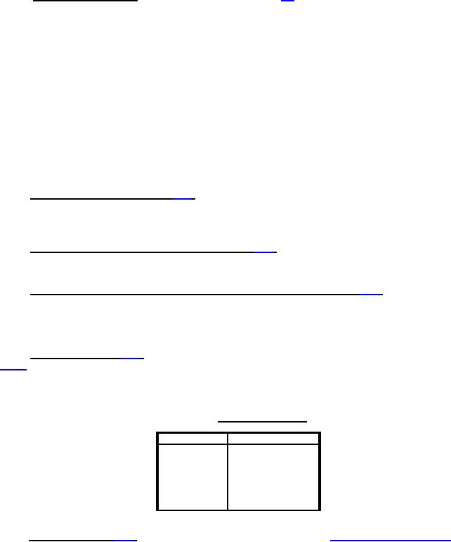
TABLE XIII. Static values of force.
Thread size
Force in pounds
4 - 40
5
6 - 32
30
8 - 32
35
10 - 32
40
10 - 24
40
1
/4 - 28
50
4.7.14 Thermal shock (see 3.19). Switches shall be tested in accordance with method 107 of MIL-STD-202. The
following details shall apply:
a.
Test condition: A.
b.
Measurements before and after cycling: Not applicable.
c.
Examinations after test: Switches shall be examined for mechanical and electrical damage and loosening of
rivets or other fastening devices.
22
For Parts Inquires call Parts Hangar, Inc (727) 493-0744
© Copyright 2015 Integrated Publishing, Inc.
A Service Disabled Veteran Owned Small Business