MIL-PRF-22885/108E
Inches
mm
.010
0.25
.03
0.8
.032
0.81
.18
4.6
.187
4.75
.235
5.97
.290
7.37
.49
12.4
.760
19.30
.96
24.4
1.050
26.67
NOTES:
1. Dimensions are in inches.
2. Metric equivalents are given for general information only.
3. Unless otherwise specified, tolerances are ±.010 for three place decimals and ±.03 for two place decimals.
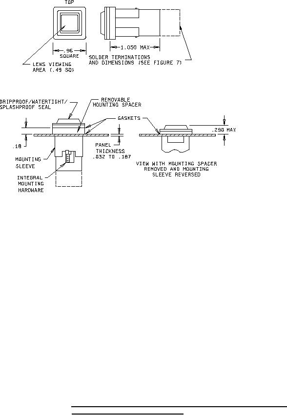
4. The mounting sleeve shall not exceed .760 square and shall be reversible so as to be usable with or
without the mounting spacer. In either case, the switch shall accommodate mounting to panels from .032
to .187 thick.
5. A mounting spacer is supplied with each switch unit for SAE-AS7788 panel requirements and places the
mounting flange flush with the top of a .235 thick edgelighted panel.
6. Spacer is to be used only for edgelighted panels, discard otherwise.
7. Pushbutton cap shall be designed to prevent incorrect insertion into switch housing.
8. Pushbutton cap shall be held captive to switch body by retaining element to prevent accidental interchange,
but shall allow replacement of the lamps.
9. Exact shape of switch is optional, provided dimensions specified are not exceeded.
10. Terminals and basic switch identification shall be permanently marked as shown on figures 7 and 9.
FIGURE 2. Switch - type II, 2 pole (enclosure design 2, 3, and 4; dripproof, watertight,
and splashproof with solder terminals).
3
For Parts Inquires call Parts Hangar, Inc (727) 493-0744
© Copyright 2015 Integrated Publishing, Inc.
A Service Disabled Veteran Owned Small Business