MIL-PRF-22885/103B
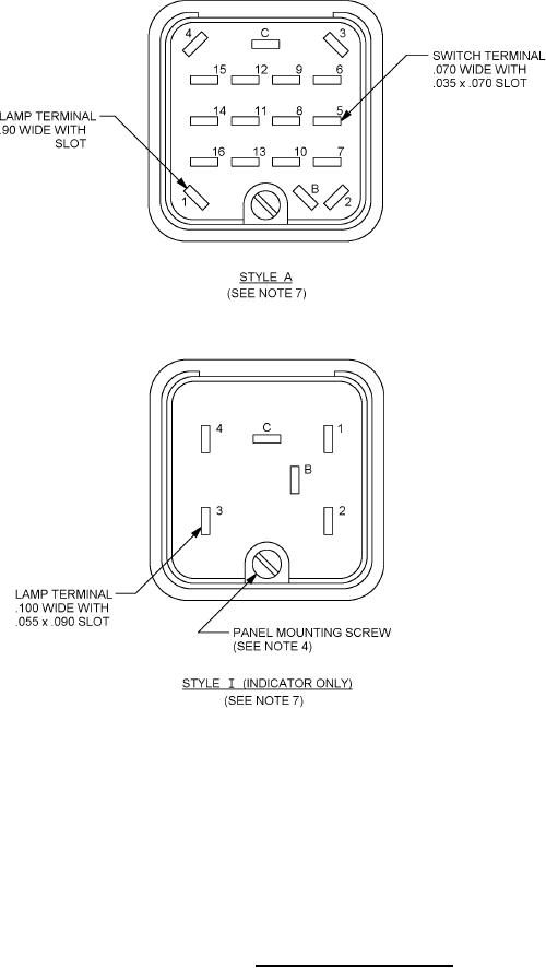
.055 x .090
Inch
mm
.035
.89
.055
1.40
.070
1.80
.090
2.29
.100
2.54
NOTES:
1. Dimensions are in inches. Metric equivalents are given for general information only.
2. Unless otherwise specified, tolerances are ±.015 (.38 mm) for three place decimals and ±.03 (.76 mm) for two
place decimals.
3. Legend area for sunlight readable pushbutton display is .591 (15.01 mm) sq.
4. Maximum recommended tightening torque is 8 inch ounces on panel mounting screw.
5. Style I (indicator) terminals are a combination solder lug and spade lug. Each terminal will accept two 20 AWG
stranded wires or a "fast-on" spade lug such as AMP #60537-1 or equivalent.
6. Unit is built with only the required terminals, see figure 2.
7. Style A and Style 1 are constructed with integral housing and switch/indicator, and do not accommodate
MIL-PRF-22885/105 plug-in-modules.
8. Metric equivalents are in parentheses.
FIGURE 1. Pushbutton switch assemblies - Continued.
4