MIL-PRF-8805/110E
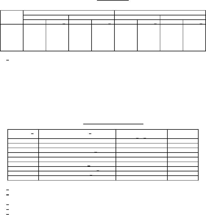
TABLE II. Electrical ratings.
Circuit schematics 3, 4, and 5
Sea level
50,000 feet
Load
28 V dc
115 V ac, 60 Hz
28 V dc
115 V ac, 60 Hz
NO or NC 2 circuit 1/
NO or NC 2 circuit 1/
NO or NC 2 circuit 1/ NO or NC 2 circuit 1/
(amperes) (amperes)
(amperes) (amperes)
(amperes) (amperes) (amperes) (amperes)
Resistive
2.5
2
2.5
2
2.5
2
2.5
2
Inductive
1.5
1
1.5
1
1.5
1
1.5
1
Motor
1.5
---
1.5
---
---
---
---
---
Lamp
.5
---
.5
---
---
---
---
---
1/ Independent loads connected to each throw.
Intermediate current: Applicable 50,000 cycles.
Low level circuit: 25,000 cycles (applicable when specified, see table III).
Logic level circuit: Applicable to electrical rating codes 4, 5, 6, and 8 (see table III).
Part or Identifying Number (PIN): See table III.
TABLE III. PIN number and characteristics.
Case style 1/
Terminal type/ 2/
Circuit schematic
Button
3/ 4/
color
electrical rating and seal
1.
Style 1
1.
Solder/power circuit/dusttight
1. 2 Term N.O.
1.
Red
2.
Style 2
2.
Solder/power circuit/watertight
2. 2 Term N.C.
2.
Black
3.
Style 3
3.
PC/power circuit/dusttight 5/
3. 3 Term N.C.
3.
Orange
5.
Style 5
4.
Solder/low level/dusttight
4. 3 Term N.O.
4.
Yellow
6.
Style 6
5.
Solder/low level/watertight
5. 5 Term two ckt
5.
Green
7.
Style 7
6.
PC/low level/dusttight 5/
6. 4 Term two ckt
6.
Blue
8.
Style 8
7.
PC/power circuit/watertight 5/
7.
Violet
8.
PC/low level/watertight 5/
8.
Gray
9.
White
1/ See figure 1 for case styles.
2/ For group A and incoming inspection, low level switches shall not be subjected to loads greater than
10 milliamperes at an open circuit voltage of 30 millivolts maximum dc or peak ac.
3/ See figure 2 for circuit schematic identification.
4/ Printed circuit board termination applies to circuit schematics 1, 2, and 6 only.
5/ Not available in circuit schematics 3, 4, and 5.
5
For Parts Inquires call Parts Hangar, Inc (727) 493-0744
© Copyright 2015 Integrated Publishing, Inc.
A Service Disabled Veteran Owned Small Business