MIL-PRF-22885/93D
NOTES
1. Dimensions are in inches.
2. Tolerances are ± .031 (±0.79 mm) unless otherwise specified.
3. Switches shall mount on .060 -.187 (1.52 -4.75 mm) panel thickness.
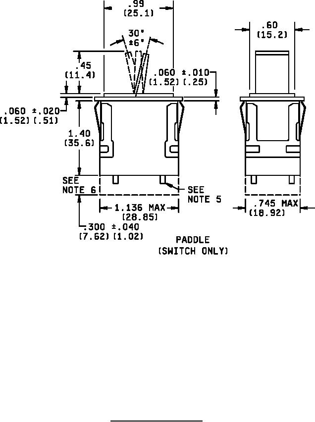
4. The design configuration is optional within envelope dimensions shown.
5. .059 ± .015 (1.50 ± 0.38 mm) high x .065 ± .021 (1.65 ± 0.53 mm) diameter standoffs are provided.
6. See figures 2 through 8 for terminal size and location.
7. Metric equivalents are given for general information only.
8. Metric equivalents are in parentheses.
9. Top side(s) of switch is shown to insure proper legend orientation (see figures 3 through 8).
See application information.
FIGURE 1. Configurations and dimensions - Continued.
5
For Parts Inquires call Parts Hangar, Inc (727) 493-0744
© Copyright 2015 Integrated Publishing, Inc.
A Service Disabled Veteran Owned Small Business