MIL-PRF-22885/93D
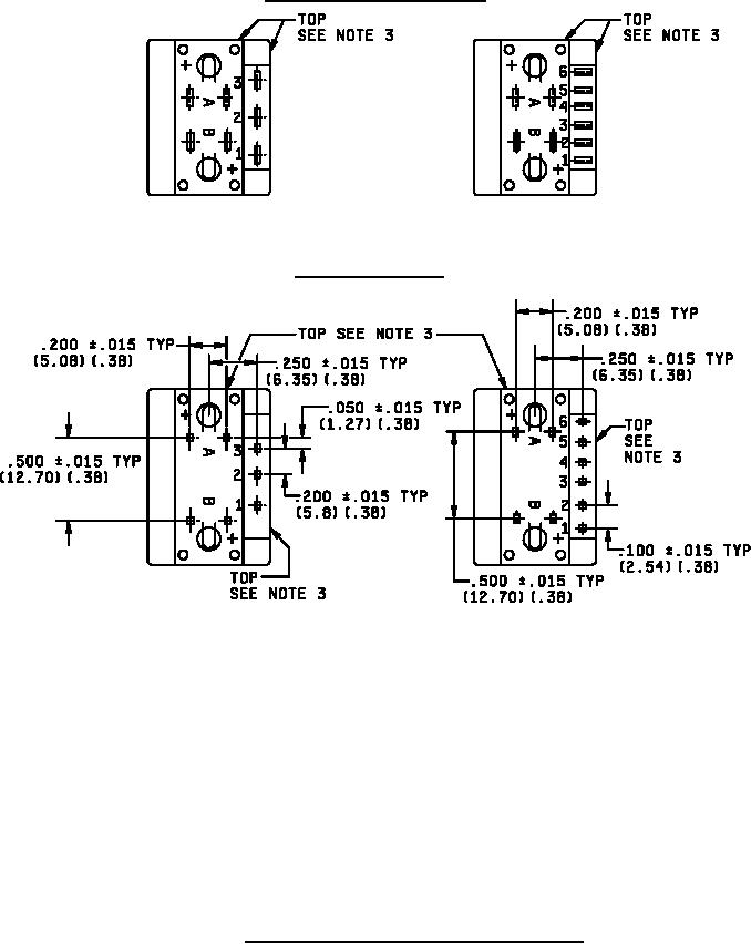
Solder or quick connect terminals
1 pole, .020 x .110 termination
2 pole, .020 x .110 termination
Printed circuit terminal
1 pole, .033 max P. C. termination
2 pole, .033 max P. C. termination
NOTES:
1. Dimensions are in inches.
2. Tolerances are ± .031 inch (± 0.79 mm) unless otherwise specified.
3. Top side of switch is shown to insure proper legend orientation. See application information.
4. Metric equivalents are given for general information only.
5. Metric equivalents are in parentheses.
6. Solder/quick connect terminals: Switch terminals shall be located relative to top sides of switch as shown.
Orientation of switch terminals is optional. Location and orientation of lamp terminals is optional.
7. Solder terminals. Minimum spacing between terminals, and minimum distance to edge of housing is
.045 inch.
FIGURE 6. Terminal location-rockers and paddles - illuminated.
11
For Parts Inquires call Parts Hangar, Inc (727) 493-0744
© Copyright 2015 Integrated Publishing, Inc.
A Service Disabled Veteran Owned Small Business