MIL-PRF-22885/86C
NOTES:
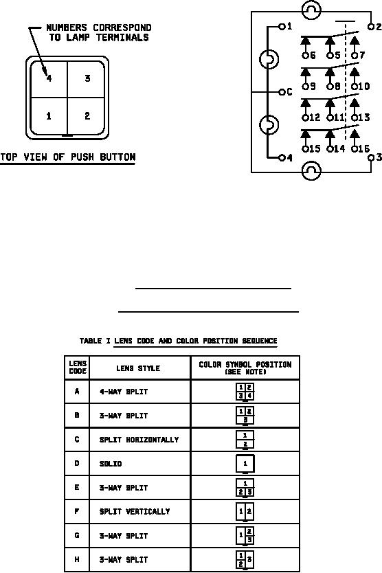
1. Terminals 8 through 13 are omitted from 2DPT configurations.
2. Terminals 5 through 16 are omitted for indicator configurations.
3. Circuit schematic shall be marked on the housing.
4. Terminals 5, 8, 11, and 14 are pole terminals.
FIGURE 2. Lamp and 4PDT switch schematic.
TABLE I. Lens code, and color position sequence.
NOTE:
1. Lens assembly removal latch is shown orientation.
3