MIL-PRF-22710H
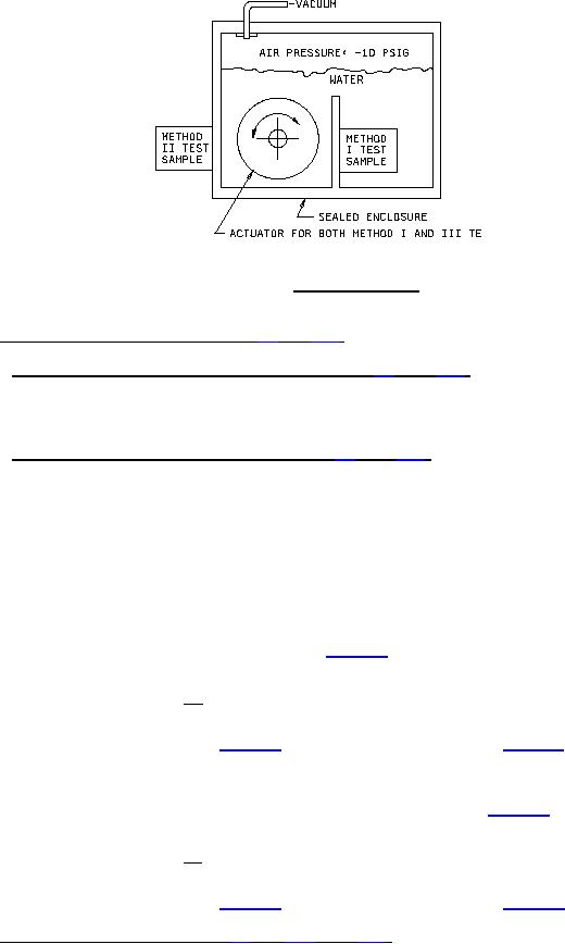
FIGURE 2. Seal test enclosure.
4.5.17.1 EMI/RFI shielding case grounding (when specified, see 3.1) (see 3.20). The switch shall be mounted by
its normal mounting means to an electrically conductive panel. The resistance shall be measured from the RFI
shielding on the switch (plated surface) to the mounting panel. The measurement shall be made using an open
circuit voltage of 6 V dc and a maximum current of 10 mA.
4.5.17.2 EMI/RFI shielding efficiency (when specified, see 3.1) (see 3.20). Switches shall be tested utilizing a test
setup or equivalent as shown on figure 3 and measurements shall be made as follows:
a. With the door open and the antenna in the "initial setup" position, establish a test level over the 200 MHz to 1
GHz range so that the received signal level is at least as many dB above the RF ambient level as that of the
shielded enclosure attenuation.
b. Record the received signal level and the signal generator output levels for the following test frequencies: 200
Hz, 225 Hz, 250 Hz, 275 Hz, 300 Hz, 325 Hz, 350 Hz, 375 Hz, 400 Hz, 600 Hz, 800 Hz, and 1,000 MHz.
c. Move the antenna to the final test positions, close the door and with an RF-tight blank panel between the
antenna, measure the integrity of the enclosure by setting the signal generator to the same output and record
the received signal level for each frequency used in 4.5.17.2b. The shielded enclosure attenuation is then
calculated using the following equation:
E1
Attenuation (dB) = 20 log
E2
d. Mount the test switch in the blank panel with the rear of the switch outside of the shielded enclosure (toward
the signal generator antenna). The switch shall be mounted as it would be for normal installation using the
mounting hardware supplied or recommended. Repeat the measurements in 4.5.17.2c and calculate the
shielding attenuation of the switch using the new receiver readings and the following formula:
E1
Attenuation (dB) = 20 log
E3
4.5.18 Acceleration (when applicable, see 3.1 and 6.2.2) (see 3.21). Switches shall be subjected to an
acceleration force of 20G attained within 2 minutes. The force shall be maintained for 1 minute in each direction
along each of its three mutually perpendicular axes. The switches shall be monitored for opening of closed contacts
and closing of open contacts with a circuit utilizing a pilot lamp. Half of the units shall be tested with the actuating
means in one position and the other half of the units shall be tested with the actuating means in an alternate position.
22
For Parts Inquires call Parts Hangar, Inc (727) 493-0744
© Copyright 2015 Integrated Publishing, Inc.
A Service Disabled Veteran Owned Small Business