MIL-PRF-22885/56H
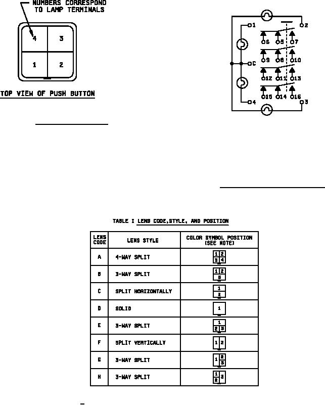
FIGURE 2. Top view of push button.
NOTES:
1. Terminals 5, 8, 11 and 14 are pole terminals.
2. Terminals 8 through 13 are omitted for 2 PDT
configurations.
3. Terminals 5 through 16 are omitted for indicator
configurations.
FIGURE 3. Lamp and 4 PDT switch schematic.
1/ Lens assembly removal latch is shown for orientation.
2
For Parts Inquires call Parts Hangar, Inc (727) 493-0744
© Copyright 2015 Integrated Publishing, Inc.
A Service Disabled Veteran Owned Small Business