MIL-PRF-22885/101E
Inches
mm
Inches
mm
Inches
mm
.01
0.3
.25
6.4
.75
19.1
.03
0.8
.39
9.9
1.03
26.2
.06
1.5
.52
13.2
1.06
26.9
.15
3.8
.62
15.7
1.33
33.8
.22
5.6
.68
17.3
1.36
34.5
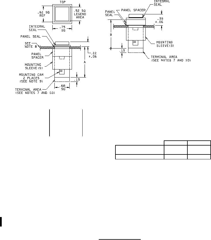
Dim. A
Dim. B
Short version
1.03 MAX
1.06 MAX
(Inactive for new design)
Extended version
1.33 MAX
1.36 MAX
NOTES:
1.
Dimensions are in inches.
2.
Metric equivalents are given for general information only.
Unless otherwise specified, tolerances are ±.03 (±.8 mm).
3.
4.
Pushbutton shall be designed to prevent incorrect insertion into switch housing.
5.
Pushbutton shall be held captive to switch body by retaining element to prevent accidental interchange.
6.
Exact shape of switch optional provided that dimensions specified are not exceeded.
7.
Solder lug terminals shall be turreted.
8.
Switches shall be capable of mounting in panel thicknesses of .030 to .250 inch (.8 to 6.4 mm).
9.
Mounting cams may be located top and bottom (as shown) or on sides.
10. Printed circuit and plug-in versions are category II items and are available from sources listed on the
qualified products list. See MIL-DTL-24317 for multistation versions.
FIGURE 2. Switch, dripproof sealed.
2
For Parts Inquires call Parts Hangar, Inc (727) 493-0744
© Copyright 2015 Integrated Publishing, Inc.
A Service Disabled Veteran Owned Small Business