MIL-PRF-22710/17J
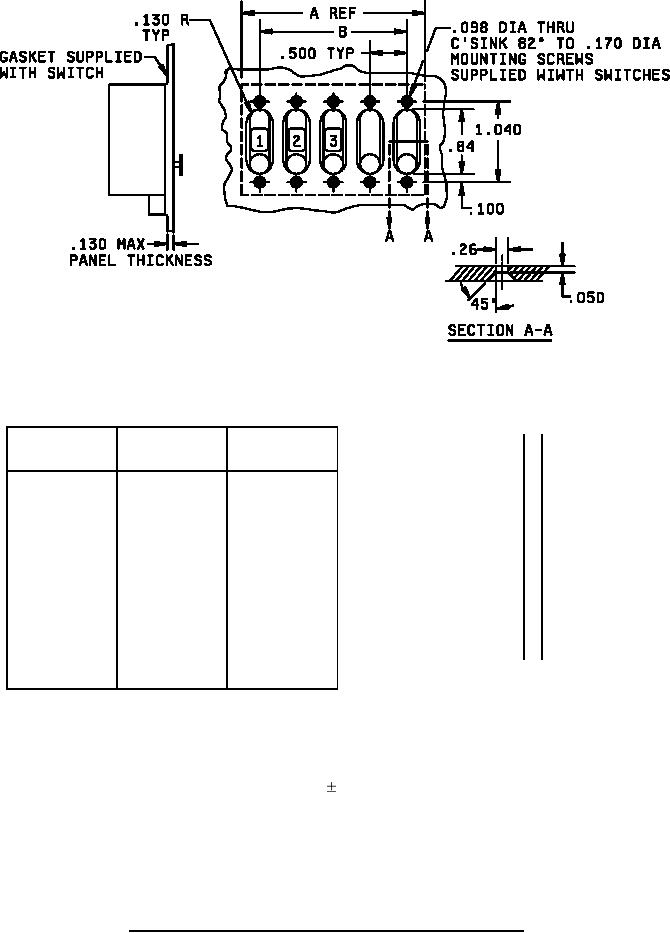
PANEL CUTOUT DETAIL WITH SWITCH INSTALLED
A
Number of
Inches
mm
Inches
mm
B
Modules
.005
0.13
.260
6.60
Ref
.050
1.27
.420
10.70
1
0.50 ( 12.70)
-
.098
2.49
.480
12.19
2
1.00 ( 25.40)
.50 (12.70)
.100
2.54
.500
12.70
3
1.50 ( 38.10)
1.00 ( 25.40)
.130
3.30
.840
21.30
.140
3.56
.945
24.00
4
2.0 ( 50.80)
1.50 ( 38.10)
.170
4.32
1.040
26.42
5
2.50 ( 63.50)
2.0 ( 50.80)
.175
4.45
1.160
29.46
6
3.00 ( 76.20)
2.50 ( 63.50)
.205
5.21
1.260
32.00
7
3.50 ( 88.90)
3.00 ( 76.20)
.215
5.46
1.310
33.27
.230
5.84
1.385
35.18
8
4.0 (101.60)
3.50 ( 88.90)
.250
6.35
1.540
39.10
9
4.5 (114.30)
4.0 (101.60)
10
5.0 (127.00)
4.5 (114.30)
NOTES:
1. Dimensions are in inches.
2. Millimeters are in parentheses.
3. Metric equivalents are given for general information only.
4. Unless otherwise specified, tolerance is 0.010 (0.25).
5. Applicable to illuminated switches only. Allowance for lighting terminals for externally
replaceable lamps, when internal lighting is specified.
6. Housing, mounting, surface and actuator are metal constructed.
7. Switch case and dial pivot shall be made of a material that allows the switch to meet the
performance requirements of this specification."
8. Mounting holes shall provide at least three full threads, tapped into the aluminum front panel.
FIGURE 1. Style SRPC17 switch and panel cutout and installation data - Continued.
2