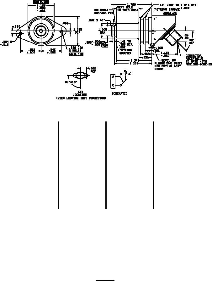
MIL-DTL-9395/10F
MIL-PRF-81329
Inches
mm
Inches
mm
Inches
mm
Inches
mm
.002
0.05
.135
3.43
.531
13.49
1.162
29.51
.005
0.13
.141
3.58
.560
14.22
1.183
30.05
.010
0.25
.188
4.78
.562
14.27
1.220
30.99
.015
0.38
.190
4.83
.656
16.66
1.312
33.32
.020
0.51
.204
5.18
.670
17.02
1.315
33.40
.03
0.76
.219
5.56
.719
18.26
1.354
34.39
.031
0.79
.25
6.4
.750
19.05
1.531
38.89
.032
0.81
.265
6.73
.812
20.62
1.562
39.67
.060
1.52
.266
6.76
.822
20.88
1.67
42.4
.062
1.57
.328
8.33
.828
21.03
1.750
44.45
.063
1.60
.389
9.88
.842
21.39
1.80
45.7
.09
2.3
.420
10.67
.996
25.30
1.850
46.99
.094
2.39
.433
11.00
1.000
25.40
1.933
49.10
.100
2.54
.46
11.7
1.005
25.53
2.54
64.5
.107
2.72
.469
11.91
1.016
25.81
2.87
72.9
.125
3.18
.489
12.42
1.156
29.36
4.40
111.8
NOTES:
1. Dimensions are in inches.
2. Metric equivalents are given for general information only and are based upon 1.00 inch = 25.4 mm.
3. Unless otherwise specified, tolerances are XX ±.03 and XXX ±.010.
4. All "O" ring grooves 32 rms maximum surface finish.
5. Contour of switches optional provided maximum dimensions specified are not exceeded.
FIGURE 1. Switches - Continued.
3
For Parts Inquires call Parts Hangar, Inc (727) 493-0744
© Copyright 2015 Integrated Publishing, Inc.
A Service Disabled Veteran Owned Small Business