MIL-DTL-3950/14A
Inches
mm
Inches
mm
Inches
mm
Inches
mm
Inches
mm
Inches
mm
Inches
mm
.005
.13
.030
.76
.250
6.35
.530
13.46
.870
22.10
1.270
32.26
1.640
41.66
.010
.25
.040
1.02
.270
6.86
.570
14.48
.910
23.11
1.340
34.04
1.660
42.16
.015
.38
.138
3.51
.370
9.40
.635
16.13
.940
23.88
1.460
37.08
1.812
46.02
.020
.51
.150
3.81
.380
9.65
.730
18.54
1.160
29.46
1.510
38.35
2.200
55.88
NOTES:
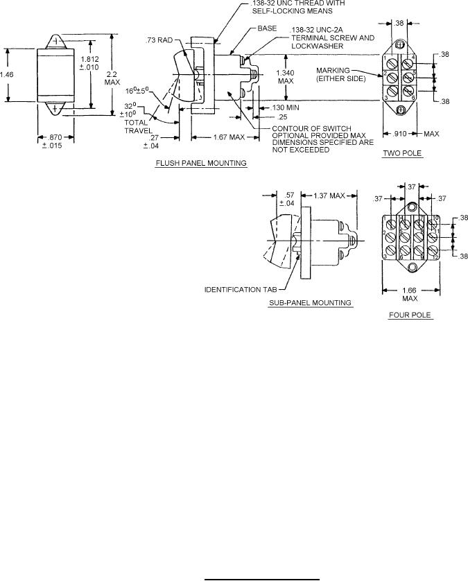
1. Dimensions are in inches.
2. Metric equivalents are given for general information only.
3. Unless otherwise specified, tolerance is ± .02 (0.51 mm) for two place decimals and ± .005
(0.13 mm) for three place decimals.
4. For terminal screw details see MIL-DTL-3950 appendix.
5. Thread length and hole depth should be such that screws will not bottom when tightened.
6. Direction of internal mechanism movement is opposite to direction of rocker movement.
FIGURE 2. Two and four pole switch.
2