MIL-DTL-3786/40B
1.
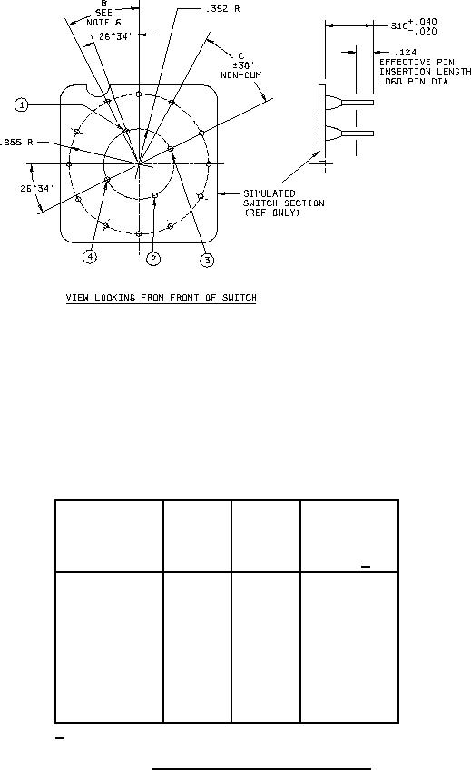
Common terminal #1.
2.
Common terminal #2.
3.
Common terminal #3.
4.
Common terminal #4. Common #1 (only) required for one pole switch. Commons #1 and #2 (only)
required for two pole switch. Common #1, #2, #3, and #4 required for four pole switch.
RECOMMENDED PC BOARD HOLE PATTERN
Required
Switching
Angle
C
number of
characteristics
of
Angle
PC board
throw
between
holes 1/
holes
30°
15°
Shorting
24
30°
30°
Non Shorting
12
15°
15°
Shorting
24
22°30'
11°15'
Shorting
32
22°30'
22°30'
Non Shorting
16
11°15'
11°15'
Shorting
32
1/ Plus required common terminal holes.
FIGURE 2. PC board hole locations and pattern.
2
For Parts Inquires call Parts Hangar, Inc (727) 493-0744
© Copyright 2015 Integrated Publishing, Inc.
A Service Disabled Veteran Owned Small Business