INCH-POUND
MIL-DTL-3786/40B
19 November 2004
SUPERSEDING
MIL-S-3786/40A
21 December 1982
DETAIL SPECIFICATION
SWITCH, ROTARY, OPEN CONSTRUCTION. ½ AMPERE AND LOW LEVEL
STYLE SR40
Inactive for new design after 8 March 1999
=
This specification is approved for use by all
Departments and Agencies of the Department of Defense.
The complete requirements for acquiring the switch described herein shall consist of this specification
and MIL-DTL-3786.
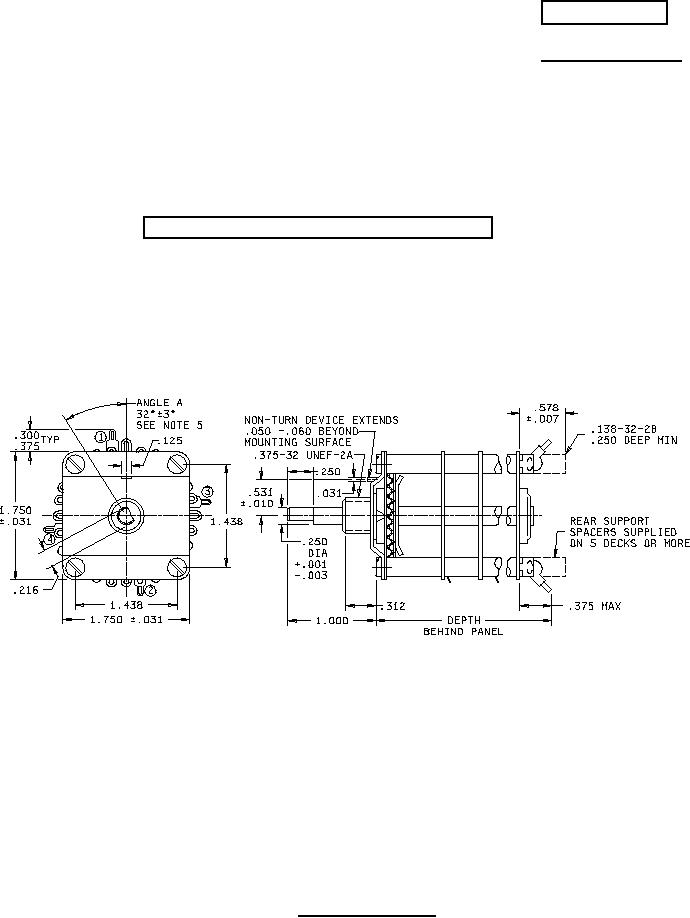
NOTES:
1. Dimensions are in inches.
2. Metric equivalents are given for general information only are based upon 1.00 inch = 25.4 mm.
3. Unless otherwise specified, tolerances are ±.015 (.38 mm) for three place decimals.
4. The number of decks is as specified. See table V.
5. Angle A is formed by two lines which intersect at the center of the shaft - one through the center of
the projected non-turn device; the other perpendicular to the shaft flat with the shaft in position 1.
6. Angle B locates #1 position from center lines as shown. Angle B is 30° for switches with angle of
throw of 15° or 30°. Angle B is 33° 45' for switches with angle of throw of 11.25° or 22.5°.
7. Unless otherwise specified, angular tolerance is ±1°.
FIGURE 1. Style SR40 switches.
AMSC N/A
FSC 5930
For Parts Inquires call Parts Hangar, Inc (727) 493-0744
© Copyright 2015 Integrated Publishing, Inc.
A Service Disabled Veteran Owned Small Business