MIL-DTL-3786/28E
NOTES:
1. Dimensions are in inches.
2. Metric equivalents are given for general information only and are based upon 1.00 inch = 25.4 mm.
3. Unless otherwise specified, tolerance are ±.015 (0.38 mm) for three place decimals, ±3° on angles,
(non-accumulative).
4. Bushing keyway .066 (1.67 mm) ±.005 (.13 mm) wide by .036 (.91 mm). ±.003 (.08 mm) deep
measured from a .375 (9.53 mm) diameter is provided for sealed shaft and bushing switches
(construction symbol F).
5. For sealed shaft and bushing switches (construction symbol F), integral tab shall not be furnished.
6. RESISTOR MOUNTING PLATES: Two resistor mounting plates shall be made of corrosion resistant
steel, and shall be of the configuration shown on figure 2. These plates are designed to allow
alinement of switch position 1 with full counterclockwise stop of resistor (viewed from shaft end).
Only one of the two plates provided with switch is to be used in adapting switch to resistor.
7. VARIABLE RESISTORS: Variable resistors shall be in accordance with the styles covered in MIL-PRF-
94/3 or MIL-PRF-94/5with N (standard type bushings, and SL type operating shafts for MIL-PRF-94/3 SB
type operating shafts for MIL-PRF-94/5.
8. Switches having more than 2.750 inch (69.85 mm) length from mounting surface are provided with
through bolts extended .250 inch (6.35 mm) minimum beyond the nuts securing the last switch
section at the rear of the switch to provide means to support the rear of the switch..
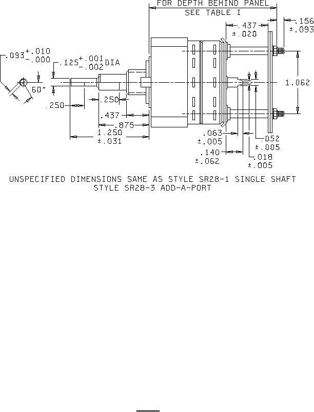
FIGURE 1. Switch - Continued.
3