MIL-DTL-3786/28E
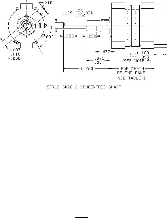
Style SR28-2 Concentric shaft
NOTES:
1. Dimensions are in inches.
2. Metric equivalents are given for general information only and are based upon 1.00 inch = 25.4
mm.
3. Unless otherwise specified, tolerance are ±.015 (0.38 mm) for three place decimals, ±3° on
angles and fractions ± .015 (.38 mm).
4. Switches having more than 2.750 inch (69.85 mm) length from mounting surface are provided
with through bolts extended .250 inch (6.35 mm) minimum beyond the nuts securing the last
switch section at the rear of the switch to provide means to support the rear of the switch.
5. Dimensions to provide rear support for switches with eleven or more wafers.
6. Bushing keyway .066 (1.67 mm) ±.005 (.13 mm) wide by .036 (.91 mm). ±.003 (.08 mm) deep
measured from a .375 (9.53 mm) diameter is provided for sealed shaft and bushing switches
(construction symbol F).
7. For sealed shaft and bushing switches (construction symbol F), integral tab shall not be
furnished.
8. Odd and even wafers are counted from shaft end (front) of switch.
FIGURE 1. Switch - Continued.
2