MIL-PRF-8805/92D
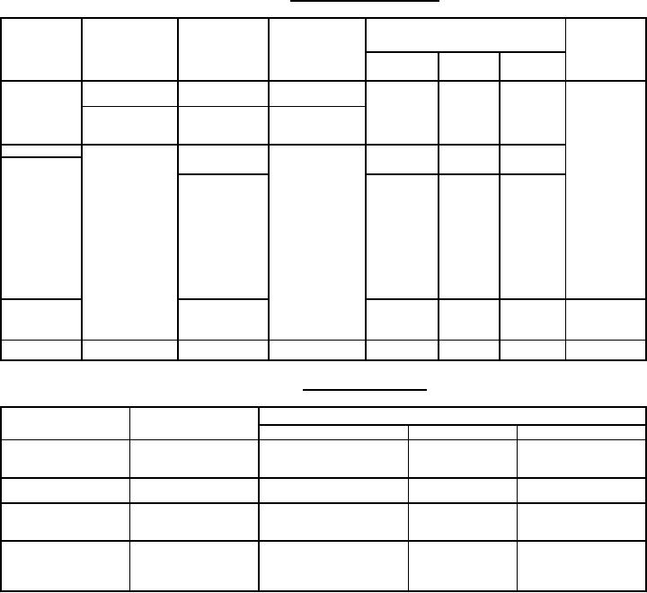
TABLE I I I . PIN's and characteristics.
Switch
Table IV
Locking
configuration
PIN
Switch action
circuit
combination
Weight
number
Opposite
Center
Keyway
configuration
(See figure I)
M8805/92-
keyway
lb. max
.075
001
1
D
1
.100
002
D
.100
Main
None
Main
003
4
3
F
.100
004
G
.075
005
E
Mom
Main
Mom
.075
006
.075
007
A
.075
008
D
.075
009
E
.075
010
F
.075
2
011
G
.075
1
012
Main
Main
Main
J
.075
013
K
.075
014
L
.075
015
M
N
.075
B
016
Mom
Main
Main
.075
E
017
.075
P
018
019
2
A
3
Main
Main
Main
.090
TABLE IV. Circuit configuration.
Circuit closed with the toggle lever in
Circuit
Switch pole
configuration
number
Opposite keyway side
Center
Keyway side
None
C-NO
C-NC
1
1
C-NO
C-NC
2
1
C-NO
C-NC
C-NC
2
2
C-NC
C-NC
C-NO
C-NC
C-NC
C-NO
1
C-NO
C-NC
C-NC
3
2
C-NC
C-NC
C-NO
3
C-NO
C-NC
1
C-NO
C-NC
4
2
C-NO
None
C-NC
3
C-NO
C-NC
4
Referenced documents. In addition to MIL-PRF-8805, this document references the following:
MIL-PRF-8805/2
MIL-STD-202
Marginal notations are not used in this revision to identify changes with respect to the previous issue due
to the extent of the changes.
6
For Parts Inquires call Parts Hangar, Inc (727) 493-0744
© Copyright 2015 Integrated Publishing, Inc.
A Service Disabled Veteran Owned Small Business