MIL-PRF-8805/84F
Inches
mm
Inches
mm
Inches
mm
Inches
mm
Inches
mm
.002
0.05
.06
1.5
.125
3.18
.352
8.94
.68
17.3
.003
0.08
.062
1.57
.187
4.75
.375
9.53
.69
17.5
.005
0.13
.068
1.73
.19
4.8
.380
9.65
.765
19.43
.010
0.25
.078
1.98
.250
6.35
.384
9.75
.85
21.6
.015
0.38
.080
2.03
.292
7.42
.500
12.70
.88
22.4
.02
0.5
.09
2.3
.300
7.62
.535
13.59
.882
22.40
.022
0.56
.093
2.36
.315
8.00
.562
14.27
.97
24.6
.025
0.64
.109
2.77
.32
8.1
.625
15.88
36.00
914.4
.030
0.76
.112
2.84
.320
8.13
.640
16.26
38.00
965.2
.031
0.79
.120
3.05
NOTES:
1. Dimensions are in inches.
2. Metric equivalents are given for general information only.
3. Unless otherwise specified, tolerances are ±.02 (0.5 mm) on two place decimals and ±.010 (0.25 mm)
on three place decimals.
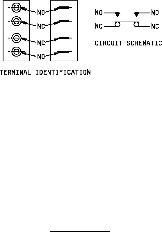
4. Terminal designation:
M8805/84-001, M8805/84-002, M8805/84-003: NO and NC stamped on bottom or either side of
switch. M8805/84-004, M8805/84-005, M8805/84-006: NO-20 and NC-20 stamped on leads. The
marking shall be legible, permanent, shall not impair the wire characteristics, shall appear every 15
inches (381. mm) maximum, and shall appear within three inches (76.2 mm) of the end.
5. Switch design optional within envelope dimensions shown.
FIGURE 1. Dimensions and configurations - Continued.
5
For Parts Inquires call Parts Hangar, Inc (727) 493-0744
© Copyright 2015 Integrated Publishing, Inc.
A Service Disabled Veteran Owned Small Business