MIL-PRF-8805/80G
NOTES:
1. Dimensions are in inches.
2. Metric equivalents are given for general information only.
3. Unless otherwise specified, tolerances are ±.03 (0.8 mm) for one place decimals and ±.02 (0.5
mm) for two place decimals, ±.005 (0.13 mm) for three place decimals
4. Configuration optional provided specified dimensions are not exceeded.
5. Lead wire shall be marked at intervals of 3.5 inches (89 mm) maximum with switch circuit
identification number followed by wire gauge number (1-20). The marking shall be legible,
permanent, and shall not impair the wire characteristics.
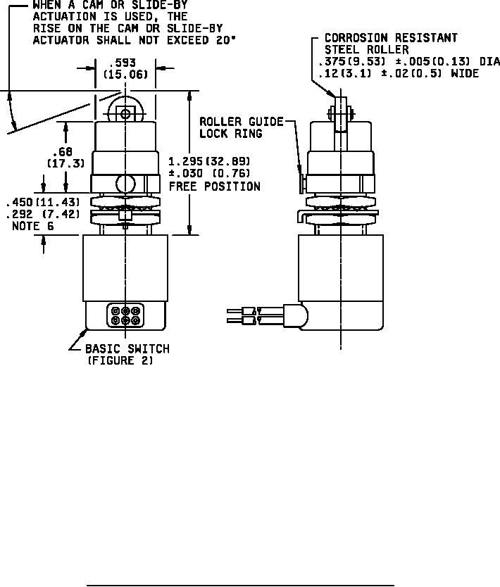
6. Roller guide shall permit positioning and locking of plunger in increments of 45º azimuth. Roller
guide location can vary between .292 (7.42 mm) and .450 (11.43 mm) while maintaining .125
(3.18 mm) minimum overtravel.
7.
Metric equivalents are in parentheses.
FIGURE 3. Roller plunger switch with .469 inch (11.91 mm) threaded bushing.
3
For Parts Inquires call Parts Hangar, Inc (727) 493-0744
© Copyright 2015 Integrated Publishing, Inc.
A Service Disabled Veteran Owned Small Business