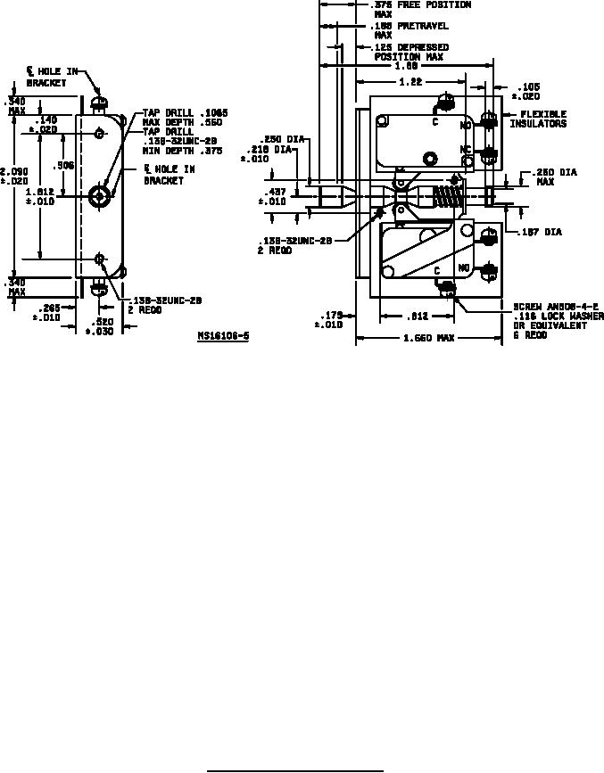
MIL-PRF-8805/56G
Inches
mm
Inches
mm
Inches
mm
Inches
mm
Inches
mm
.010
.25
.156
3.96
.250
6.35
.437
11.10
1.200
30.48
.020
.51
.175
4.45
.26
6.60
.500
12.70
1.22
30.99
.030
.76
.179
4.55
.265
6.73
.520
13.21
1.300
33.02
.050
1.27
.187
4.75
.30
7.62
.578
14.68
1.530
38.86
.058
1.47
.188
4.78
.340
8.64
.650
16.51
1.590
40.39
.100
2.54
.19
4.83
.350
8.89
.812
20.62
1.660
42.16
.105
2.67
.203
5.16
.355
9.02
.906
23.01
1.812
46.02
.110
2.79
.218
5.54
.375
9.53
.98
24.89
1.88
47.75
.125
3.18
.220
5.59
.39
9.91
1.000
25.40
2.090
53.09
.140
3.56
.230
5.84
.406
10.31
1.10
27.94
NOTES:
1. Dimensions are in inches.
2. Metric equivalents are given for general information only and are based upon 1 inch = 25.4 mm.
3. Unless otherwise specified, tolerances are ±.005 (.13 mm) for three place decimals and ±.02 (.51 mm)
for two place decimals.
4. Notch in actuator rod will permit up to .038 (.97 mm) displacement between the rod and the hole in the
bracket in the free position on MS16106-1, MS16106-2, MS16106-3 and MS16106-5 and up to .062
(1.57 mm) displacement between the rod and the hole in the bracket when the rod is fully extended on
MS16106-4.
5. Exact shape of switch assembly optional provided dimensions are not exceeded. Internal
configuration optional.
6. Positive overtravel stop shall be provided on the rod for operation in either direction.
7. Push to operate. Returns automatically to position shown. Pull to operate. Remains in operated
position until reset for automatic return by next full stroke `push' operation.
8. All switches shall be permanently fixed to the assembly.
9. Military Standard Drawing MS16106 is canceled and superceded by MIL-PRF-8805/56.
FIGURE 1. Dimensions and configuration - Continued.
3
For Parts Inquires call Parts Hangar, Inc (727) 493-0744
© Copyright 2015 Integrated Publishing, Inc.
A Service Disabled Veteran Owned Small Business