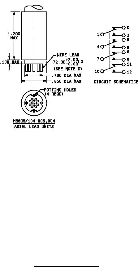
MIL-PRF-8805/104D
Inches
mm
Inches
mm
Inches
mm
Inches
mm
.003
0.08
.12
3.05
.469
11.91
1.000
25.40
.004
0.10
.130
3.30
.47
11.94
1.100
27.94
.015
0.38
.15
3.81
.475
12.07
1.125
28.58
.030
0.76
.17
4.32
.525
13.34
1.200
30.48
.072
1.83
.250
6.35
.700
17.78
1.375
34.93
.093
2.36
.375
9.53
.850
21.59
1.719
43.66
.100
2.54
.432
10.97
.895
22.73
2.0
50.80
72.0
1828.80
NOTES:
1. Dimensions are in inches.
2. Unless otherwise specified, tolerances are ±.03 (0.76 mm) for two place decimals, ±.010
(.25 mm) for three place decimals, and 1/2° for angles.
3. Metric equivalents are given for general information only.
4. Contour optional provided maximum dimensions specified are not exceeded.
5. The marking (identification and circuit schematic) shall be permanently and legibly marked
on the switch case in the location shown (on side of case opposite keyway).
6. Wire leads shall be marked at 3.0 inch intervals with switch circuit identification number
followed by wire gage number (1-20, 2-20, 3-20, etc.).
7. Hex nut shall be MS21340-04 or equivalent. Alternative base metals and protective
finishes, as approved by the qualifying activity, may be utilized for hardware material.
FIGURE 1 Dimensions and configurations - Continued.
3
For Parts Inquires call Parts Hangar, Inc (727) 493-0744
© Copyright 2015 Integrated Publishing, Inc.
A Service Disabled Veteran Owned Small Business