MIL-PRF-8805/1E
Inches
mm
Inches
mm
Inches
mm
Inches
mm
Inches
mm
Inches
mm
.001
.03
.063
1.60
.177
4.50
.375
9.53
.750
19.05
1.184
30.07
.002
.05
.085
2.16
.210
5.33
.469
11.91
.859
21.82
1.187
30.15
.003
.08
.090
2.29
.219
5.56
.520
13.21
.917
23.29
1.937
49.20
.020
.51
.094
2.39
.250
6.35
.625
15.88
.984
24.99
2.422
61.52
.025
.64
.140
3.56
.326
8.28
.630
16.00
1.000
25.40
2.437
61.90
.032
.81
.150
3.81
.344
8.74
.687
17.45
1.110
28.19
2.469
62.71
.046
1.17
.156
3.96
.359
9.12
.719
18.26
1.125
28.58
NOTES:
1. Dimensions are in inches.
2. Metric equivalents are given for general information only.
3. Unless otherwise stated, tolerance is ±.015 (0.38 mm).
4. Exact shape of switch optional provided dimensions specified are not exceeded.
5. Terminals: Captive construction or equivalent.
a. Screw terminals are supplied with lockwashers and No. 6-32 NC-2A, Fil HD, binder HD, or pan HD screws.
b. Solder lug terminals shall accommodate one No. 14 AWG wire.
6. Mounting holes shall accept .139 (3.53 mm) maximum diameter pins or screws on 1.000 ±.002 (25.40 ±.05 mm)
centers.
7. Switch terminal surface shall be free of plastic flash and may extend .030 (.76 mm) maximum beyond plastic body
surface.
8. Actuators may be permanently affixed by threading into the plastic cover.
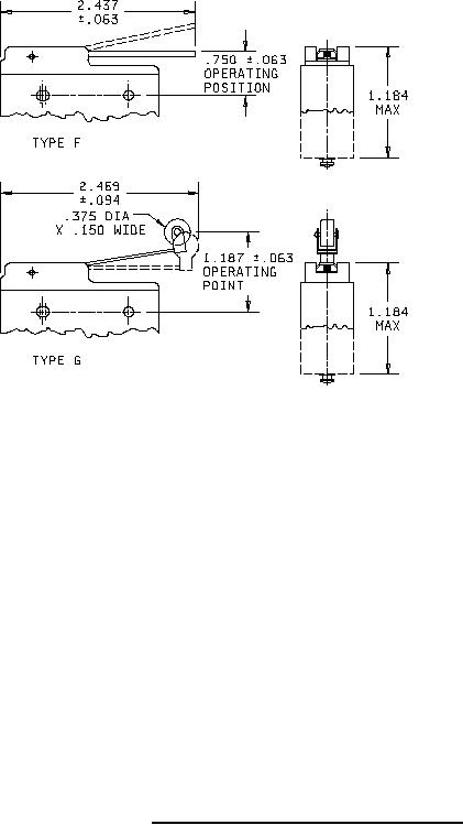
FIGURE 1. Dimensions and configurations -Continued.
3