MIL-PRF-22885/87C
NOTES:
1. Dimensions are in inches.
2. Metric equivalents are given for general information only.
3. Unless otherwise specified, tolerance is .016 inch (0.41 mm).
4. Terminal design is optional.
5. The design configuration is optional within envelope dimensions shown.
6. Mounting means to accumulate .050 inch (1.27 mm) to .250 inch (6.35 mm) panel thickness.
7. Design of lamp module locking device optional.
8. Lamp circuit schematic shall be marked on the indicator housing as shown on figure 6.
9. Lamp terminals shall be permanently identified with letters as shown on figure 6. Exact position of
lamp terminals is optional. Relative positions shall be in accordance with figure 6 herein.
10. Design of switch retaining device is optional. Must interface with all previously qualified
MIL-PRF-22885/86 switch assemblies.
FIGURE 1. Switch, pushbutton, illuminated - Continued.
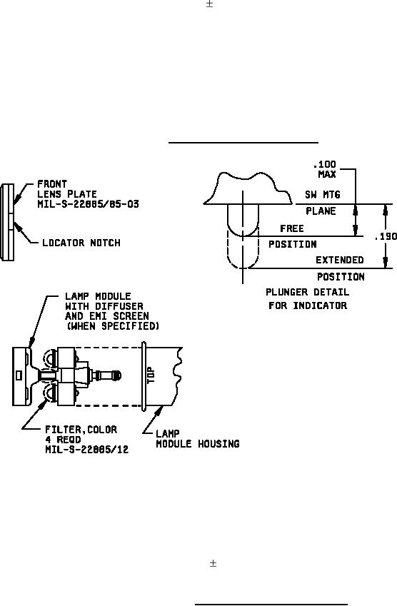
Inches
mm
.100
2.54
.190
4.83
NOTES:
1. Dimensions are in inches.
2. Metric equivalents are given for general information only.
3. Unless otherwise specified, tolerances are .005 (.013 mm).
4. Retention of lamp module to housing is optional (for relamping).
FIGURE 2. Lamp module and plunger detail.
2