MIL-PRF-22885/110C
Inches
mm
Inches
mm
.10
2.5
.680
17.27
.14
3.6
.75
19.1
.53
13.5
2.25
57.2
.63
16.0
NOTES:
1. Dimensions are in inches.
2. Metric equivalents are given for information only.
3. Unless otherwise specified, tolerance are ±.010 (± 0.25 mm) for three place decimals and ±.03 (±
0.8 mm) for two place decimals.
4. Spacer used in front of mounting panel provides for mounting in conjunction with standard
.200/.240 (5.08/6.10 mm) thick edge lighted panel. Same spacer used in rear of mounting panel
provides for mounting without edge lighted panel.
5. Spacer supplied with this assembly is .100 (2.54 mm) thick for unsealed application. Spacer
supplied for sealed application is .070 (1.78 mm) thick.
6. Panel seal, supplied with switch when required, always mounts against front of mounting panel.
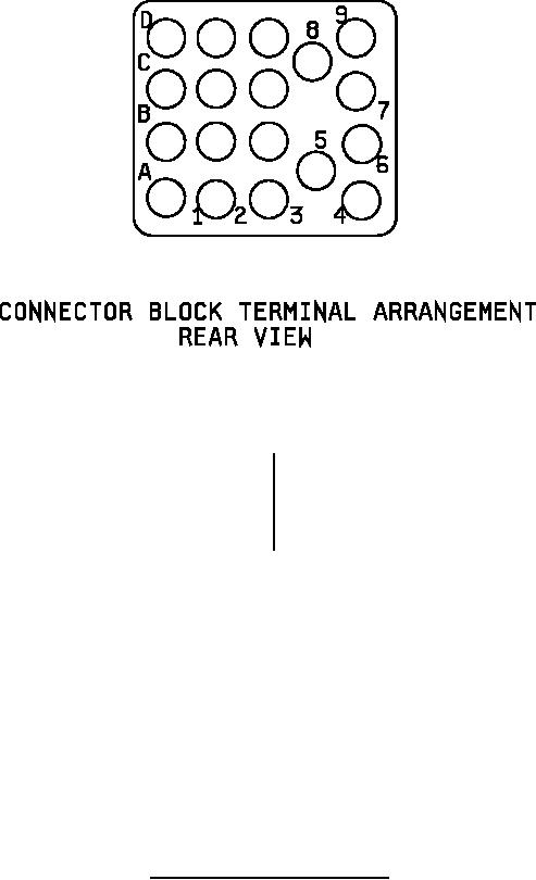
7. Connector block accepts wire terminal M39029/1-100, not supplied with switch.
8. Pushbutton shall be designed to prevent incorrect insertion into switch housing.
9. Pushbutton shall be held captive to switch body by retaining element to prevent accidental
interchange.
10.
Exact shape of switch is optional provided dimensions specified are not exceeded.
FIGURE 1. Switch dimensions and configuration - Continued.
2
For Parts Inquires call Parts Hangar, Inc (727) 493-0744
© Copyright 2015 Integrated Publishing, Inc.
A Service Disabled Veteran Owned Small Business