MIL-DTL-83731/22C
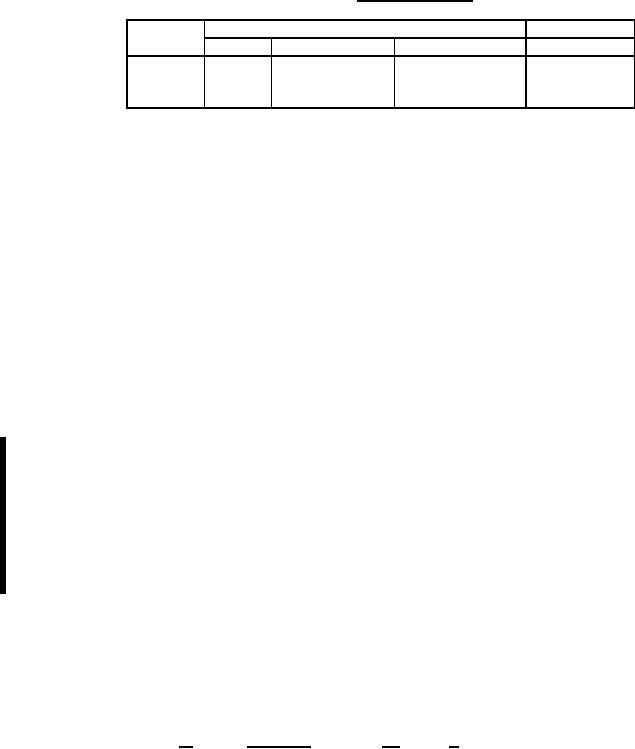
TABLE I. Electrical ratings.
Type of
High level (current in amperes)
Logic level
load
28 V dc 125 V ac, 60 Hz 115 V ac, 400 Hz
5 V dc
Resistive
5
5
5
0.010 ampere
Inductive
2
2
2
--
Lamp
1
1
1
--
High level resistive load (dc and ac): 10,000 cycles. Altitude testing not applicable.
Logic level load: 10,000 cycles, tested in accordance with ANSI/EIA RS-448, method 17. Rate of
actuation in accordance with MIL-DTL-83731 electrical endurance. Fifty percent of test cycles at room
ambient conditions. Fifty percent of test cycles at 71ºC, +4º, -0ºC. No "sticks" or "misses" allowed.
Inductive load (dc and ac): 10,000 cycles. Altitude testing not applicable.
Lamp load: Switches shall make and break the rated lamp load for 10,000 operating cycles.
Intermediate current: Not applicable.
Short circuit: Use 100 amperes at 28 V dc.
Flux sealed: The sealing is obtained when the base is sealed to prevent flux from entering the switch
case during the wave soldering process.
Flux seal test: Three additional switches shall be tested as follows during qualification and group B
inspection: Measure and record initial contact resistance. Place switches, terminals down, into a shallow
pan. Pour flux at 80ºF ±5ºF, type RMA of J-STD-004, specific gravity 0.896, into pan without splashing
until level of flux is approximately 1/16 inch above the bottom of the plastic switch case and let switches
soak for 10 minutes. Remove switches from flux, clean with flux cleaning solvent and immediately put
into oven for drying at 175ºF for two hours. After switches have cooled to room temperature, repeat initial
measurement. Contact resistance shall not increase by more than 10 milliohms over the initial reading.
Disassemble and visually examine the contact area for evidence of flux. Any evidence of flux shall be
cause for rejection.
Sand and dust: Not applicable.
Explosion: Not applicable.
Part number: The part number shall consist of the prefix M83731/22followed in order by the appropriate
two-digit number from table II and the number from table III as shown in the following example:
M
83731/22
-
71
1
|
|
|
|
|
|
|
|
Number from table III denotes
Military designation___|
|
|
|_____
the switch is with solder
|
|
lug terminals.
Specification sheet number_______|
|_____________
Number from table II denotes
switch has ON-OFF-ON circuit
with all directions locked.
5
For Parts Inquires call Parts Hangar, Inc (727) 493-0744
© Copyright 2015 Integrated Publishing, Inc.
A Service Disabled Veteran Owned Small Business