MIL-DTL-83731/21B
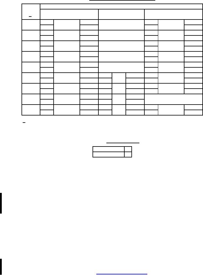
TABLE II. Circuit for switching characteristic.
Circuit with toggle in
Circuit
Toward flat
Opposite flat
1/
Center
(down position)
(up position)
1-2
7-8
2-3
8-9
21
ON
OFF
ON
4-5
10-11
5-6
11-12
1-2
7-8
2-3
8-9
23
ON
NONE
ON
4-5
10-11
5-6
11-12
1-2
7-8
2-3
8-9
26
MOM-ON
NONE
ON
4-5
10-11
5-6
11-12
1-2
7-8
2-3
8-9
27
MOM-ON
OFF
MOM-ON
4-5
10-11
5-6
11-12
1-2
7-8
2-3
8-9
31
MOM-ON
OFF
ON
4-5
10-11
5-6
11-12
1-2
7-8
2-3
8-9
2-3
8-9
32
ON
2-3
ON
4-5
10-11
4-5
10-11
5-6
11-12
1-2
7-8
2-3
8-9
2-3
8-9
33
MOM-ON
2-3
ON
4-5
10-11
4-5
10-11
5-6
11-12
1-2
7-8
2-3
8-9
34
MOM-ON
ON
NONE
4-5
10-11
5-6
11-12
1-2
7-8
2-3
8-9
2-3
8-9
35
MOM-ON
ON
ON
4-5
10-11
4-5
10-11
5-6
11-12
1/ Circuit numbers 32, 33, and 35 replace and are interchangeable with circuits previously
identified as 41, 42, and 43 respectively.
TABLE III. Termination type.
Solder lug
1
Printed circuit
2
Reference Documents
MIL-DTL-83731
ANSI/EIA RS-448
MIL-STD-202
J-STD-004
The margins of this specification are marked with vertical lines to indicate where modifications from this
revision were made. This was done as a convenience only and the Government assumes no liability
whatsoever for any inaccuracies in these notations. Bidders and contractors are cautioned to evaluate
the requirements of this document based on the entire content irrespective of the marginal notations.
Custodians:
Preparing activity:
Navy - EC
DLA - CC
Air Force - 85
DLA - CC
(Project 5930-2008-053)
NOTE: The activities listed above were interested in this document as of the date of this document.
Since organizations and responsibilities can change, you should verify the currency of the information
above using the ASSIST Online database at https://assist.daps.dla.mil/ .
6