MIL-DTL-83731/10D
Inches
mm
Inches
mm
Inches
Mm
Inches
mm
Inches
mm
Inches
mm
0.001
0.03
0.025
0.635
0.047
1.19
0.155
3.94
0.3
7.62
0.465
11.81
0.002
0.05
0.025
0.79
0.05
1.27
0.185
4.7
0.316
8.03
0.468
11.89
0.003
0.08
0.03
0.76
0.06
1.52
0.189
4.8
0.32
8.13
0.51
12.95
0.005
0.13
0.031
0.79
0.065
1.65
0.19
4.83
0.4
10.16
0.577
14.66
0.01
0.25
0.032
0.81
0.075
1.91
0.225
5.72
0.41
10.41
0.61
15.49
0.02
0.51
0.04
1.02
0.08
2.03
0.25
6.35
0.43
10.92
0.685
17.4
0.021
0.53
0.046
1.17
0.115
2.92
0.253
6.43
0.44
11.18
0.705
17.9
NOTES:
1. Dimensions are in inches.
2. Metric equivalents are given for general information only.
3. Unless otherwise specified, tolerance is ± .005 (0.13 mm).
4. Direction of internal mechanism movement is opposite to direction of toggle movement.
5. Mounting bushing is D-shaped.
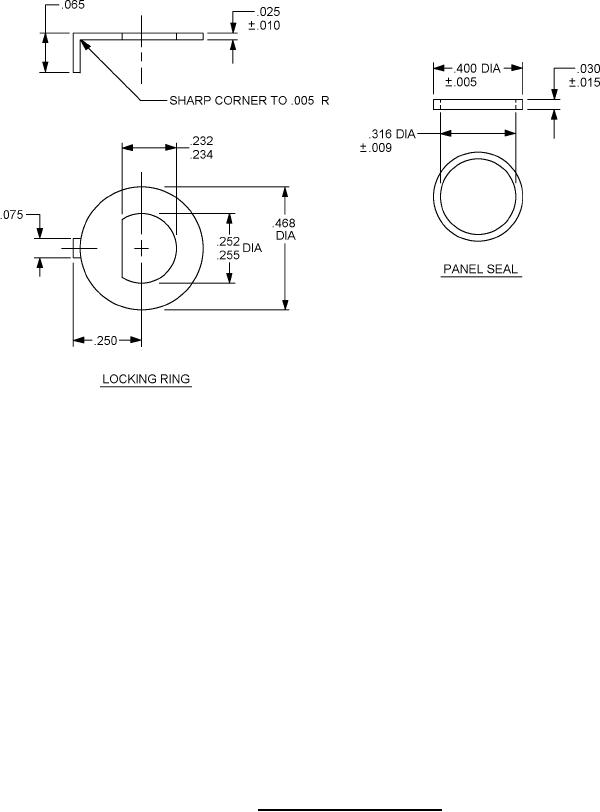
6. To insure proper sealing by panel seal, locking ring should be used on front of panel only.
FIGURE 3. Locking ring and panel seal.
3