MIL-DTL-3786/9E
REQUIREMENTS:
Dimensions and configuration: See figures 1 and 2.
Angle of throw: 15° and 30° (see table V).
Terminals: The terminals tabs shall be bent at an angle of 60° ±15° from the plane of the section.
When flat terminals are required, the dimensions shall be as shown on figure 1.
Rotational torque: The minimum and maximum values of torque determined for shaft rotation shall be
within the limits specified in table I.
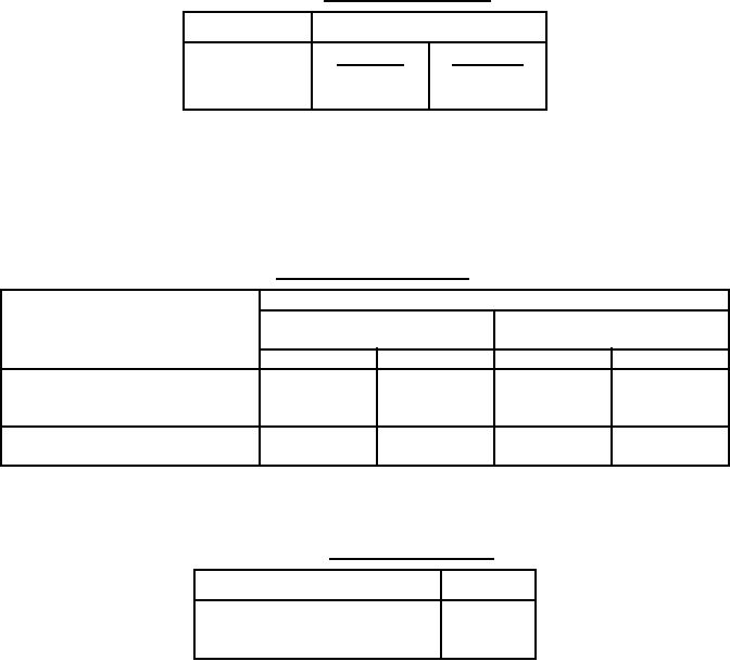
TABLE I. Rotational-torque limits.
Temperature
Torque (lb-in)
Minimum
Maximum
Room
2
6
Minimum
2
8
Construction: N or S.
Life (rotational): The test loads for the applicable circuit conditions shall be as specified in table II.
Each of the loads specified for the applicable environmental condition shall be switched by at least one
rotor contact of the switch.
TABLE II. Electrical loads.
Loads
Inductive
Environmental condition
Resistive
(2.8 henries)
Milliamperes
Volts, dc
Milliamperes Volts, dc
500
28
At atmospheric pressure
50
28
250
115 V rms
50
300 V rms
---
---
350
28
At reduced barometric pressure
100
115 V rms
Dielectric withstanding voltage: The applicable test voltage specified in table III shall be applied
between the general switch elements.
TABLE III. Dielectric-test voltages.
Altitude
Volts, rms
At atmospheric pressure
1,000
At reduced barometric pressure
400
Mounting hardware: Each switch shall be supplied with one hexagon nut in accordance with
MS25082-20 or equivalent, and one internal-tooth lockwasher in accordance with NASM35333-42 or
equivalent.
5
For Parts Inquires call Parts Hangar, Inc (727) 493-0744
© Copyright 2015 Integrated Publishing, Inc.
A Service Disabled Veteran Owned Small Business