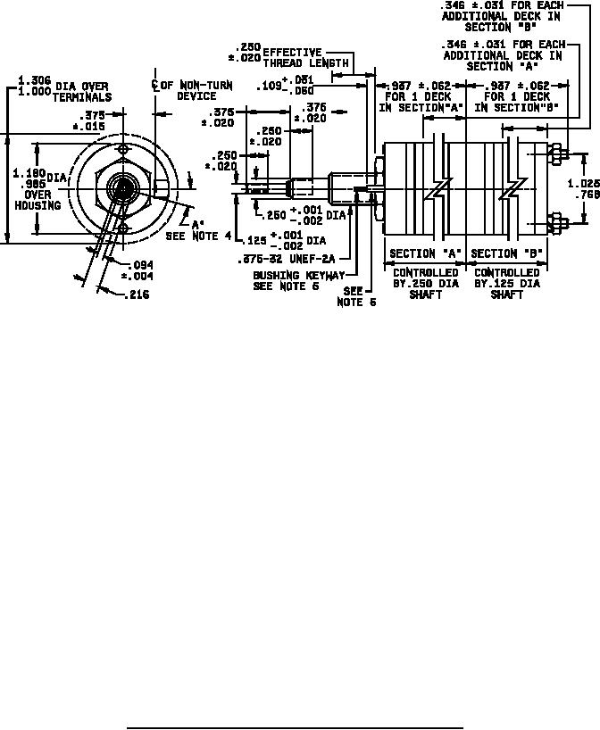
MIL-DTL-3786/4M
Inches
mm
Inches
mm
Inches
mm
.001
0.03
.062
1.57
.375
9.53
.002
0.05
.094
2.39
.768
19.51
.004
0.10
.109
2.77
.937
23.80
.015
0.38
.125
3.18
.985
25.02
.020
0.51
.216
5.49
1.000
25.40
.031
0.79
.250
6.35
1.025
26.04
.060
1.52
.346
8.79
1.180
29.97
1.306
33.17
NOTES:
1. Dimensions are in inches.
2. Metric equivalents are given for general information only.
3. Unless otherwise specified, tolerances are ±.005 (0.13 mm) and ±3° on angles, (nonaccumulative).
4. Shaft-flat angle A° is the angle between a line through the center of the shaft and center of the nonturn
device, and another line through the center of the shaft and perpendicular to the shaft flat, with switch in the
extreme counterclockwise position. Each shaft-flat is defined in the same way. The shaft-flat angles A° for
the .125 (3.18 mm) and the .250 (6.35 mm) diameter shafts may be the same or different angles. This refers
to panel position; see figure 2 for terminal location.
5. Bushing keyway .069 (1.75 mm) ±.005 (0.13 mm) wide by .036 (0.91 mm) ±.003 (0.08 mm) deep measured
from a .375 (9.53 mm) diameter.
6. For sealed shaft and bushing switches, integral tab shall not be furnished. Busing keyway shall be used for
nonturn characteristic.
FIGURE 1. Dimensions and configurations (style SR04-2, concentric shaft) - Continued.
2