MIL-DTL-3786/32C
NOTES:
1. Dimensions are in inches.
2. Metric equivalents (to the nearest .01 mm) are given for general information only and are based upon
1 inch = 25.4 mm.
3. Unless otherwise specified, tolerance is ±.015 (.38 mm).
4. The number of sections is indicated in table II.
5. Nonturn device as shown is not applicable to S construction switches.
6. Shaft shown in maximum counterclockwise position for switches with stop and with switch in position
No. 1 for switches without stop.
7. Angle "A" is formed by two lines radiating from the shaft center, and in the mounting plane of the
switch. One line is parallel to a radial line perpendicular to the shaft flat with the switch in position 1.
The other line passes through the center of the nonturn device. Angle "A" is 90°.
8. Unless otherwise specified, tolerance on angles is ±3°.
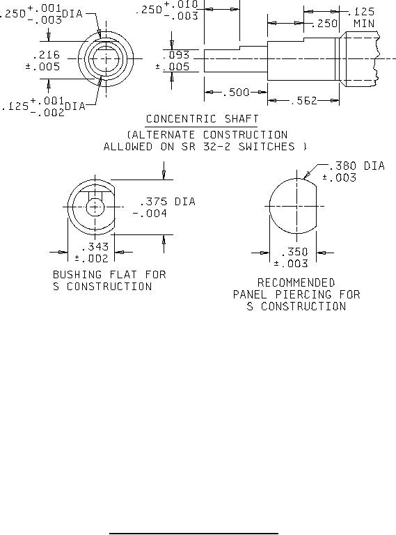
FIGURE 1. Styles SR32-1 and SR32-2 switches - Continued.
2
For Parts Inquires call Parts Hangar, Inc (727) 493-0744
© Copyright 2015 Integrated Publishing, Inc.
A Service Disabled Veteran Owned Small Business