MIL-DTL-21604/7C
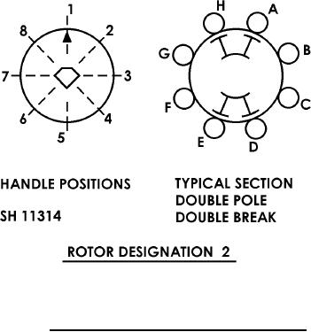
NOTE: Viewed from the handle end.
FIGURE 2. Rotor contact configuration and handle positions.
REQUIREMENTS:
Dimensions and configuration: See figure 1, figure 2, and table I.
Angle of throw: 45 degrees.
Switching action:
JR 304: Detent.
JRM 300: Switch provides for spring return from position 6 to position 1, and from position 4 to position 1.
Internal stops and stop mechanisms are not available and the use of external stops is required to limit travel
to a lesser number of positions.
Electrical loads:
AC current: 10 amperes.
Voltage: 125 volts (at 60 - 400 Hz, 0.80 inductive power factor).
Temperature rise: 30C maximum.
Contact material:
Rotor: Silver-overlay phosphor bronze.
Stator: Silver-overlay copper.
Barriers: See figure 1.
Terminal marking: See figure 1.
Stop marking: See figure 1.
Qualification samples: See table II.
3