MIL-DTL-15291G
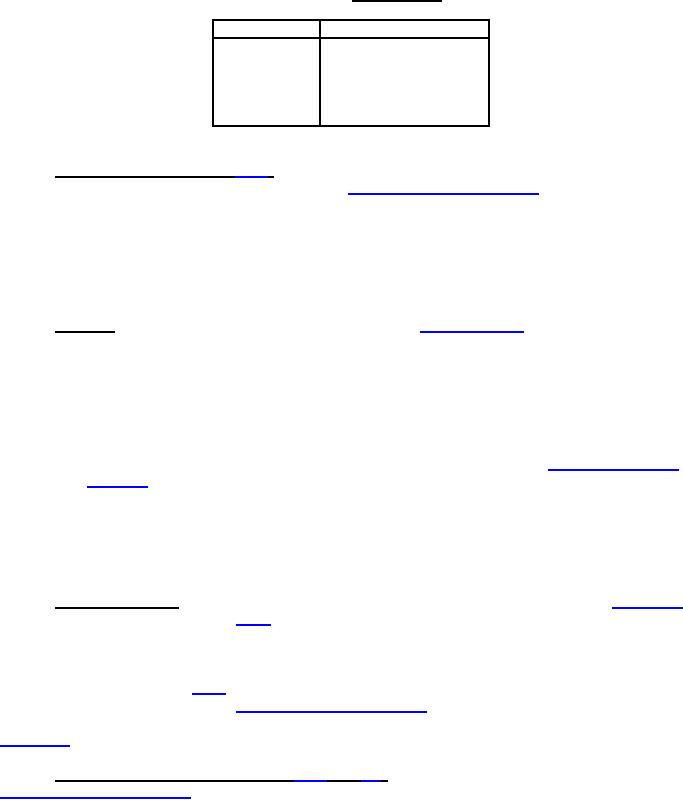
TABLE VII. Stop strength.
Switch class
Torque (inch-pounds)
1SR
30
1SRN
50
3SR
100
6SR
100
20SR
100
4.7.2 Salt spray (corrosion) (see 3.6.2). Switches with their mounting hardware, assembled with their
mounting means, shall be tested in accordance with method 101 of MIL-STD-202. The following details
shall apply:
a. Test condition - B
b. Measurements after exposure - Not applicable.
After the test, switches shall be examined for evidence of excessive corrosion. Mounting and terminal
hardware shall be removable at the end of the test.
4.7.3 Vibration. Switches shall be tested in accordance with MIL-STD-167-1, type I. The following
details and exceptions shall apply:
a. Test and measurements prior to vibration - Not applicable
b. Method of mounting - Switches shall be rigidly mounted by their normal mounting means.
The mounting fixture shall be free from resonance over the test frequency range. Rear
support shall be provided with switches having 10 or more decks, including blank decks.
c. Direction of motion - One of the directions of vibration shall be in a plane perpendicular to
the longitudinal axis of the switch.
d. Electrical test conditions - The test circuit shall be in accordance with method 310 of MIL-
STD-202, and shall consist of all closed mated contacts in an ON switch position. At the
option of the manufacturer, contacts may be wired in series.
e. Test measurements during vibration - Contacts shall be monitored for opening.
f. Measurements after vibration - Not applicable.
g. Examination after test - Switches shall be examined for change in shaft position, and
evidence of broken, loose, deformed, or displaced parts.
4.7.4 High-impact shock. High-impact shock tests shall be conducted in accordance with MIL-S-901
for grade A, class I equipment (see 3.6.4). Rear support shall be provided with switches having 10 or
more decks, including blank decks. The switch shall be energized in an operating position at rated
voltage. The coil of a relay calibrated for the rated voltage of the switch being tested and having a drop-
out time of 0.02 second, shall be connected in series with the energized contacts of the switch to
determine conformance with 3.6.4. An alternate monitoring method using a calibrated timing device and
a supervisory test current similar to method 310 of MIL-STD-202 may be substituted for the calibrated
relay method. A latching type circuit shall be connected to an energized normally open contact during the
MIL-S-901 testing. The latching of this circuit will indicate that the contact is momentarily closed.
4.7.5 Dielectric withstanding voltage (see 3.6.5 and 6.2). The switch shall be tested in accordance with
method 301 of MIL-STD-202. The following details shall apply:
a. For switches rated at 125 volts ac (V ac), the test voltage shall be 1250 volts root means
square (rms). For switches rated at 500 V ac the test voltage shall be 2000 volts rms.
b. For group A inspection, the test voltage shall be applied for 5 seconds. For qualification and
groups B and C inspections, the test voltage shall be applied for 1 minute.
c. In each switch position, the test voltage shall be applied between open circuits contacts, and
between closed contacts and noncurrent carrying parts.
12
For Parts Inquires call Parts Hangar, Inc (727) 493-0744
© Copyright 2015 Integrated Publishing, Inc.
A Service Disabled Veteran Owned Small Business