MIL-PRF-8805/3L
.375
Inches
mm
Inches
mm
Inches
mm
Inches
mm
.001
0.03
.031
0.79
.250
6.35
.623
15.82
.004
0.10
.047
1.19
.312
7.92
.625
15.88
.006
0.15
.062
1.57
.333
8.46
.640
16.26
.015
0.38
.094
2.39
.375
9.53
.688
17.48
.016
0.41
.125
3.18
.438
11.13
.739
18.77
.019
0.48
.156
3.96
.500
12.70
.875
22.23
.020
0.51
.187
4.75
.562
14.27
1.375
34.93
.022
0.56
.188
4.78
NOTES:
1.
Dimensions are in inches.
Unless otherwise stated, tolerance is .010 (0.25 mm).
2.
3.
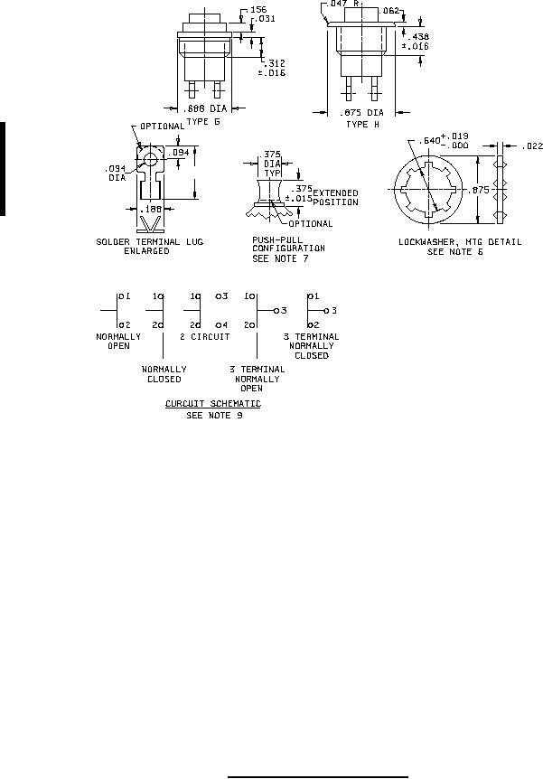
Mounting thread .625-24 UNEF-2A applies to type C, F, G, and H. All threads to be within .10
2.54 mm) of shoulder.
4.
All terminal threads are .086-56UNC-28.
5.
Hardware for each terminal includes one screw, one terminal lug, and one lockwasher.
6.
Types C, F, G, and H shall be furnished with suitable mounting hardware.
7.
Overall height of switch with push-pull activator is 1.530 (38.66 mm) maximum in extended position.
8.
Metric equivalents are given for general information only.
9.
For push-pull configuration, circuit schematic is shown with actuator in extended position.
FIGURE 1. Configuration and dimensions - Continued.
2
For Parts Inquires call Parts Hangar, Inc (727) 493-0744
© Copyright 2015 Integrated Publishing, Inc.
A Service Disabled Veteran Owned Small Business