MIL-PRF-83504/4E
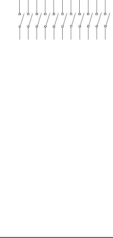
Typical contacts circuit arrangement 12 station switch.
(Contacts shown in open position)
Inches
mm
Inches
mm
.003
0.08
.067
1.70
.004
0.10
.085
2.16
.005
0.13
.090
2.29
.010
0.25
.100
2.54
.012
0.30
.160
4.06
.015
0.38
.230
5.84
.020
0.51
.270
6.86
.022
0.56
.300
7.62
.030
0.76
.340
8.64
.040
1.02
.370
9.40
.055
1.40
.405
10.29
NOTES
1. Dimensions are in inches. Metric equivalents are given for information only.
2. Each switch station is shown in the "OFF" position. Continuity is established (switch is turned "ON")
when the rocker extension nearer the number is depressed.
3. Each switch position shall be numbered as shown.
4. Exact shape of switch is optional, provided outline dimensions are not exceeded.
5. Design of terminals and standoffs are optional
FIGURE 1. Dimensions and configuration, single pole stations (SPST) - Continued.
2