MIL-PRF-22885/12H
Design and construction: See figure 1.
Intended use: For use with 4-lamp (T-1 ¾ midget flanged base) illuminated push button switches of
MIL-PRF-22885/9, MIL-PRF-22885/15 and MIL-PRF-22885/87.
Classification: See MIL-PRF-22885/9, MIL-PRF-22885/15 and MIL-PRF-22885/87.
Illuminated color: See table I. Spectrographic method shall be used.
Luminance: See table I.
Marking: Identification marking shall be on unit package or tag.
Inspection:
Group A: Inspection for dimensions.
Group B and qualification: As part of MIL-PRF-22885/9, MIL-PRF-22885/15 or MIL-PRF-22885/87
switch inspection. One additional sample (4 color filters) per color required for color fade test.
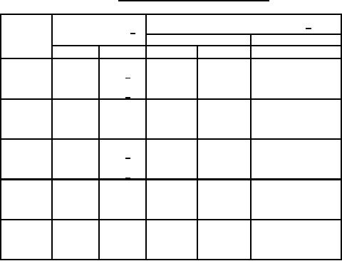
TABLE I. Illuminated color and luminance.
Illuminated color
Switch luminance (foot-lamberts) 2/
chromaticity limits 1/
Colors
2360° Kelvin
4 lamps illuminated
2 lamps illuminated
x
y
Minimum
Maximum
Minimum
.695
.285
.703
SL 3/
Red
50
100
20
.655
.325
.660
SL 3/
.260
.570
.300
.630
Green
50
100
20
.160
.660
.200
.720
.562
.415
.570
SL 3/
Yellow
100
200
40
.596
.382
.605
SL 3/
.150
.260
.220
.260
Blue
8
40
4
.220
.320
.150
.320
.400
.420
.460
.420
100
200
40
White
.400
.380
.460
.380
1. The chromaticities of the diffusing lenses or colored filters expressed
as x and y coordinates on the CIE chromaticity diagram shall lie
within areas bounded by the coordinates listed for each color, using
a source illuminate of 2360° K.
2. Switch photometric brightness, when viewed from the front of the
applicable switch indicator light.
3. SL - Spectrum locus (where intersected by other coordinate pair).
2
For Parts Inquires call Parts Hangar, Inc (727) 493-0744
© Copyright 2015 Integrated Publishing, Inc.
A Service Disabled Veteran Owned Small Business