MIL-DTL-9395/40C
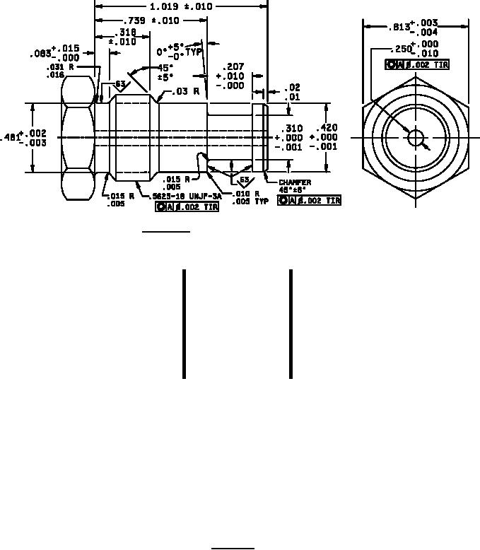
DETAIL A
Inches
mm
Inches
mm
Inches
mm
.001
0.03
.02
0.5
.318
8.08
.002
0.05
.03
0.8
.420
10.67
.003
0.08
.031
0.79
.481
12.22
.004
0.10
.055
1.40
.739
18.77
.005
0.13
.083
2.11
.813
20.65
.010
0.25
.120
3.05
1.00
25.40
.015
0.38
.207
5.26
1.019
25.88
.016
0.41
.250
6.35
2.75
69.8
.310
7.87
NOTES:
1. Dimensions are in inches.
2. Metric equivalents are given for general information only and are based upon 1.00 inch = 25.4 mm.
3. Exact shape of switch is optional provided outline dimensions specified are not exceeded and
connector location area is as specified.
4. Schematic shown is for switches with pressure ports exposed to zero lbf/in2.
5. Packing groove in accordance with MIL-G-5514.
6. Surface finish 125 roughness height reference, except where otherwise specified.
7. Surface finish IAW ASME B46.1.
8. Switch shall incorporate a redundant seal.
FIGURE 1. Switches - Continued.
2
For Parts Inquires call Parts Hangar, Inc (727) 493-0744
© Copyright 2015 Integrated Publishing, Inc.
A Service Disabled Veteran Owned Small Business