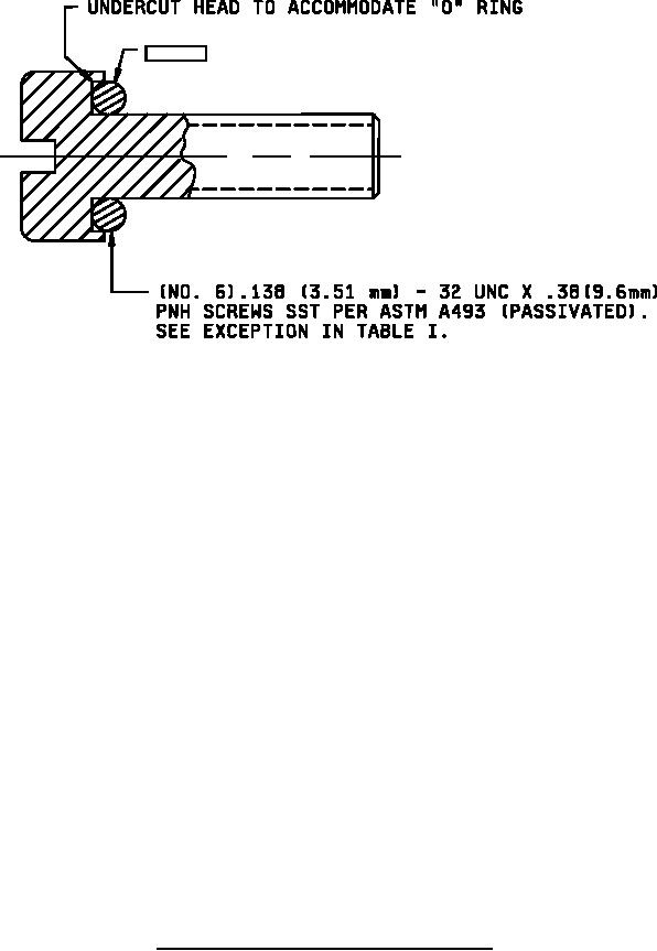
MIL-DTL-5423/14G
"0"- RING-
Inche
mm
Inche
mm
Inches
mm
Inche
mm
s
s
s
.031
0.79
.921
23.39
1.593
40.46
2.625
66.68
.05
1.3
1.000
25.40
1.781
45.24
2.656
67.46
.063
1.60
1.093
27.76
1.875
47.63
2.750
69.85
.093
2.36
1.109
28.17
2.000
50.80
2.906
73.81
.12
3.0
1.125
28.58
2.062
52.37
3.062
77.77
.16
4.1
1.343
34.11
2.125
53.98
3.093
78.56
.19
4.8
1.375
34.93
2.218
56.34
3.156
80.16
.250
6.35
1.38
35.1
2.25
57.2
3.500
88.90
.375
9.53
1.44
36.6
2.26
57.4
3.625
92.08
.843
21.41
1.46
37.1
2.31
58.7
3.656
92.86
.875
22.23
1.500
38.10
2.32
58.9
3.718
94.45
.91
23.1
1.53
38.9
2.343
59.51
3.937
100.11
4.312
109.53
4.812
122.22
NOTES:
1. Dimensions are in inches.
2. Metric equivalents are given for general information only.
3. Unless otherwise specified, tolerances are ±.02 (.51mm) for two place decimals and ±.031 (.79 mm) for three
place decimals.
4. The number of mounting screws shall be supplied as indicated.
5. Edges shall be smooth and free from burrs.
6. Alternative base metals and protective finishes, as approved by the qualifying activity, may be utilized for frame
materials.
FIGURE 1. Dimensions and configuration boots type D, style 1 Continued.
3
For Parts Inquires call Parts Hangar, Inc (727) 493-0744
© Copyright 2015 Integrated Publishing, Inc.
A Service Disabled Veteran Owned Small Business