MIL-DTL-3786/5H
NOTES:
1. Dimensions are in inches.
2. Metric equivalents are given for general information only.
3. Unless otherwise specified, tolerance is ±.015 (0.38 mm).
4. The number of sections is as selected from table III.
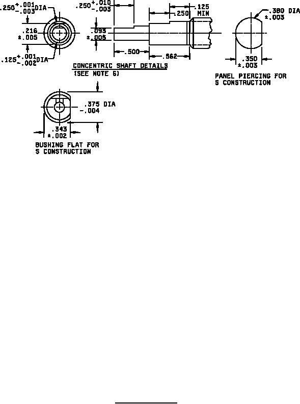
5. Nonturn device as shown is not applicable to S construction switches.
6. Inner shaft stop strength 4 inch-pounds. Outer shaft stop strength 15 inch pounds.
7. Shaft-flat angle A° is the angle between a line through the center of the shaft and center of the
nonturn device, and another line through the center of the shaft and perpendicular to the shaft
flat. For construction S switches, the bushing flat is the nonturn device. Angle A is 270°.
8. Shaft shown in maximum counterclockwise position for switches with stops, and with switch in
position number 1 for switches without stops.
9. Front plate design optional provided it falls within the maximum outside diameter of the section
dimension referenced.
10. Terminal tabs may be bent to the rear at an angle up to 75° from the plane of the section.
11. Marking plate is included with all switches.
FIGURE 1. Style SR05 switch - Continued.
2
For Parts Inquires call Parts Hangar, Inc (727) 493-0744
© Copyright 2015 Integrated Publishing, Inc.
A Service Disabled Veteran Owned Small Business