INCH-POUND
MIL-DTL-3786/41A
21 October 2001
SUPERSEDING
MIL-S-3786/41
12 August 1976
DETAIL SPECIFICATION SHEET
SWITCHES, ROTARY, CLOSED CONSTRUCTION,
0.5 AMPERE, STYLE SR41
This specification is approved for use by all Departments
and Agencies of the Department of Defense.
The complete requirements for procuring the switches described herein shall consist
of this document and the latest issue of Specification MIL-S-3786.
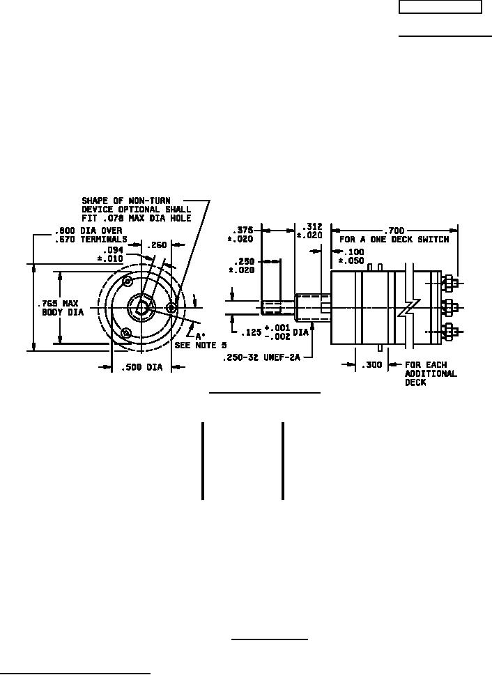
"E" CONSTRUCTION STYLE
(EXPLOSION-PROOF, CLOSED CONSTRUCTION
WITHOUT SEALED SHAFT AND BUSHING)
INCHES
MM
INCHES
MM
INCHES
MM
.001
.03
.094
2.39
.312
7.92
.002
.05
.100
2.54
.375
9.53
.010
.25
.125
3.18
.500
12.70
.020
.51
.250
6.35
.670
17.02
.050
1.27
.260
6.60
.700
17.78
.078
1.98
.300
7.62
.765
19.43
.800
20.32
NOTES:
1. Dimensions are in inches.
2. Metric equivalents (to the nearest .01 mm) are given for general information only and are based upon 1 inch =
25.4 mm.
3. Unless otherwise specified, tolerances are ±.015 (.38 mm) and 3° on angles (non-accumulative).
4. Maximum weight: one deck switch is 16 grams. Add 2.5 max grams for each additional deck and based upon 1
oz. = 28.35 grams.
5. Shaft flat angle A° is the angle between a line through the center of the shaft, and center of the nonturn device
and another line through the center of the shaft and perpendicular to the shaft flat, with switch in position
number 1. This refers to panel position; see figure 2 for terminal location.
FIGURE 1. Style SR41 switch.
AMSC N/A
1 of 9
FSC 5930
DISTRIBUTION STATEMENT A. Approved for public release; distribution is unlimited.