INCH-POUND
MIL-DTL-3786/36B
31 January 2008
SUPERSEDING
MIL-DTL-3786/36A
21 October 2001
DETAIL SPECIFICATION SHEET
SWITCH, ROTARY, CLOSED CONSTRUCTION, 1/4 AMPERE, STYLE SR36
This specification sheet is approved for use by all
Departments and Agencies of the Department of Defense.
The requirements for acquiring the product described herein shall consist of this specification sheet and
MIL-DTL-3786.
Table 1
ANGLE OF THROW
DIM. "A"
DIM. "B"
DIM. "C"
15°
1.350
1.281
1.156
18°, 22½°
1.190
1.125
1.000
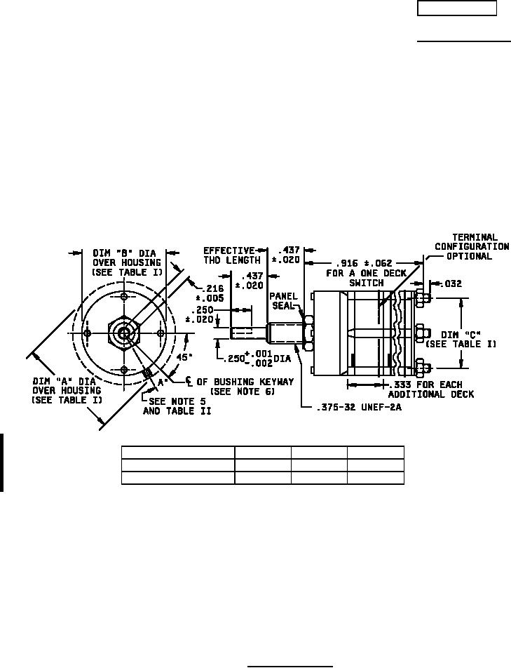
NOTES:
1. Dimensions are in inches. Metric equivalents (to the nearest .01 mm) are given for general
information only and are based upon 1 inch = 25.4 mm.
2. Unless otherwise specified, tolerances are ±.015 (.38 mm) and ±3° on angles (non-accumulative).
3. Maximum weight: One deck switch is 50 grams. Add 10 maximum grams for each additional
decks based upon 1 oz. = 28.35 grams.
4. Shaft flat angle A is the angle between a line through the center of the shaft and center of the
bushing keyway, and another line through the center of the shaft and perpendicular to the shaft flat,
with switch in Position Number 1. This refers to panel position. See Figure 2 for terminal location.
5. Bushing keyway .069 (1.75 mm) ± .005 (.13 mm) wide by .036 (.91 mm) ± .003 (0.8 mm) deep
measured from a .375 (9.53 mm) diameter.
6. Intergal tab shall not be furnished.
FIGURE 1. Style SR36 switch.
AMSC N/A
FSC 5930
For Parts Inquires call Parts Hangar, Inc (727) 493-0744
© Copyright 2015 Integrated Publishing, Inc.
A Service Disabled Veteran Owned Small Business