MIL-DTL-3786/20K
Inches
mm
Inches
mm
Inches
mm
.001
0.03
.020
0.51
.210
5.33
.002
0.05
.031
0.79
.219
5.56
.003
0.08
.032
0.81
.250
6.35
.004
0.10
.050
1.27
.260
6.60
.005
0.13
.065
1.65
.500
12.70
.007
0.18
.093
2.36
.576
14.63
.015
0.38
.125
3.18
.625
15.88
.203
5.16
.713
18.11
NOTES:
1. Dimensions are in inches.
2. Metric equivalents are given for general information only.
3. Unless otherwise specified, tolerances are ±.005 (0.13 mm) and ±3 degrees on angles
(noncummulative).
4. Shaft flat angle A° is the angle between a line through the center of the shaft perpendicular to the
mounting bushing flats and another line through the center of the shaft perpendicular to the
mounting bushing flats and another line through the center of the shaft and perpendicular to the
shaft flat with switch in position one. For slotted switches, the slot is in line with the point of contact
for pole number one.
5. Position number one and terminal number one coincide.
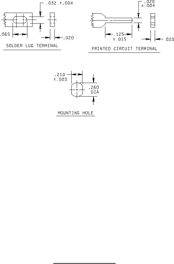
FIGURE 1. Dimensions and configurations - Continued.
3
For Parts Inquires call Parts Hangar, Inc (727) 493-0744
© Copyright 2015 Integrated Publishing, Inc.
A Service Disabled Veteran Owned Small Business