MIL-DTL-3786/13G
Inches
mm
Inches
mm
Inches
mm
.001
0.03
.203
5.16
.375
9.53
.002
0.05
.210
5.33
.505
12.83
.010
0.25
.250
6.35
.640
16.26
.020
0.51
.260
6.60
.670
17.02
.094
2.39
.268
6.81
.765
19.43
.125
3.18
.312
7.92
.800
20.32
1.010
25.65
NOTES:
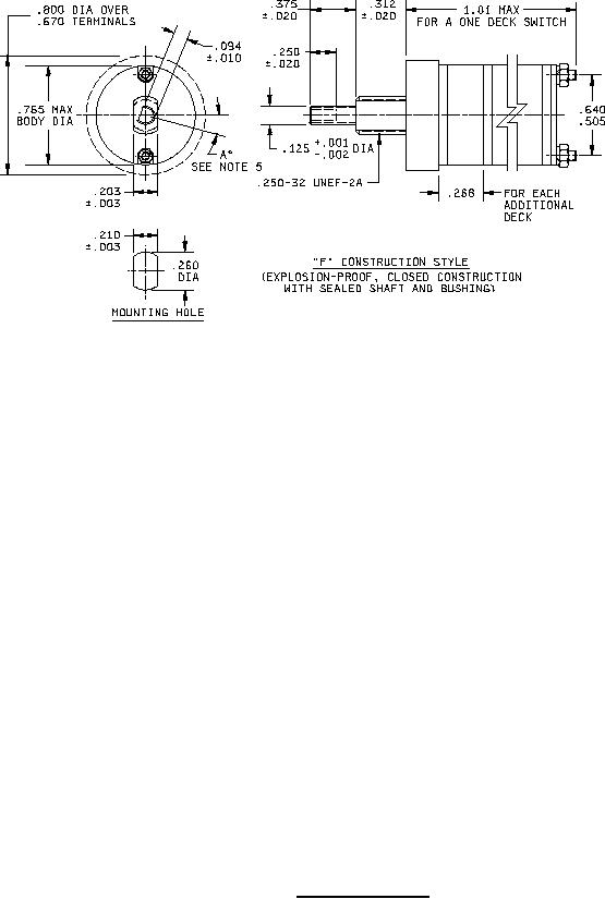
1. Dimensions are in inches.
2. Metric equivalents are given for general information only.
3. Unless otherwise specified, tolerances are ±.015 (0.38 mm) and ±3° on angles
(nonaccumulative).
4. Maximum weight: one deck switch is 19 grams. Add 2.5 max grams for each additional deck
based upon 1 oz = 28.35 grams.
5. Shaft-flat angle A° is the angle between a line through the center of the shaft, perpendicular to
the mounting bushing flats and another line through the center of the shaft and perpendicular to
the shaft flat, with switch in position No. 1. This refers to panel position; see figure 2 for terminal
location.
FIGURE 1. Style SR13 switch - Continued.
2