MIL-DTL-28827C
MIL-STD-202. The following details shall apply:
a. Test condition B.
b. Points of measurement Between all terminals and frame or ground.
of MIL-STD-202. The following details and exception shall apply:
a. Measurements Between the terminals of the contacts of the same pole forming a switching
circuit; for all poles in a switch at each of the temperature settings; between mated contacts
for all poles.
b. Test current and maximum test voltage: The test current and test voltage may be of any
values compatible with the test method employed, but shall not exceed the rated values of
the switch (see 3.1).
c. Number of activations prior to measurement Not applicable.
d. Number of test activations Three.
e. Number of measurements per activation One reading after each thermal actuation.
4.7.13 Connector torque (applicable to switches with electrical connectors) (see 3.17). Switches shall
be mounted by their normal mounting means on a rigid metal fixture. A torque of five foot-pounds shall
be applied to the electrical connectors, in a plane perpendicular to its central axis and in the direction
which would tighten the mating part, and held for one minute. If the normal mounting means of the switch
includes some type of strip or clamp which would permit rotation of the entire switch in its mounting
device during this test, the switch shall be held stationary by suitable mechanical restraints while the
torque is applied. This test is intended as a verification of connector mounting suitability, and is not
meant to conform integrity of connector design or construction. Following this test, switches shall be
tested in accordance with calibration (see 4.7.3).
4.7.14 Terminal strength (when applicable) (see 3.18). Terminals shall be tested in accordance with
4.7.14.1 or 4.7.14.2, as applicable. Unless otherwise specified (see 3.1), switches shall be mounted by
their normal mounting means.
4.7.14.1 Threaded terminals. Threaded terminals shall be subjected, for one minute to the applicable
static values for force and torque specified in table V. The force shall be gradually applied as a pull along
the axis of the threads, perpendicular to the axis of the threads, and in the direction most likely to cause
failure. The torque shall be applied in the direction which will tighten the screws.
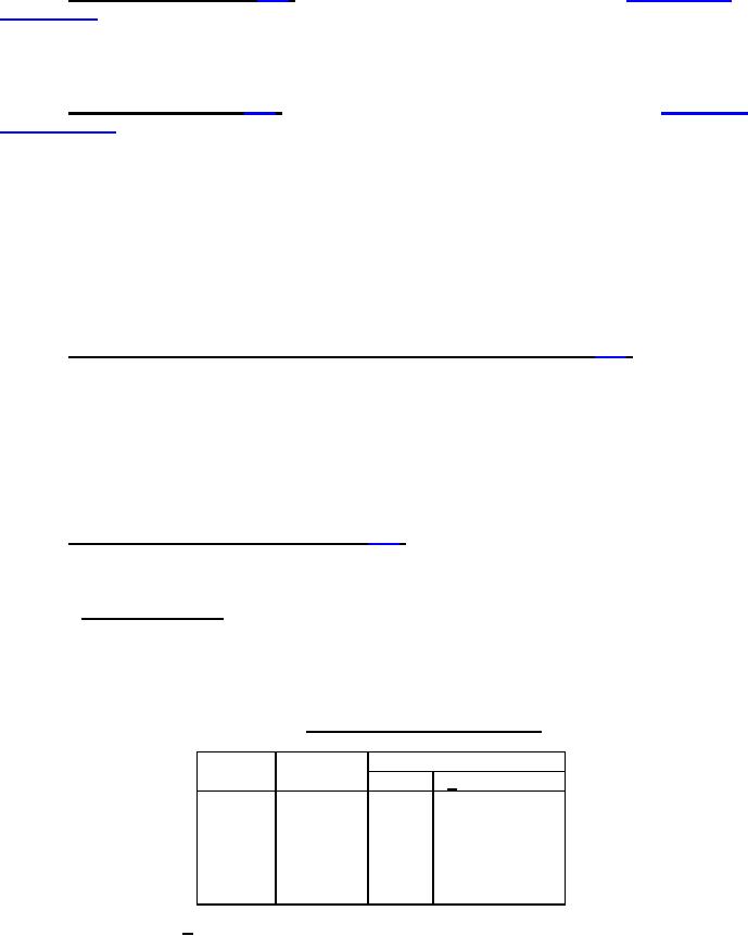
TABLE V Static values of force and torque.
Torque (inch-pounds)
Thread
Force
size
(pounds)
Steel
1/ Non-ferrous
4-40
5
8
5
6-32
30
14
10
8-32
35
22
20
10-32
40
38
32
10-24
40
42
35
1/4-28
50
100
75
1/ The torque values are intended as a test for terminals
and not for terminal hardware. Where brass terminal
screws are used, it may be necessary to substitute
steel screws for the purpose of this test as torque
values exceed shear strength of brass screws in
certain sizes.
13
For Parts Inquires call Parts Hangar, Inc (727) 493-0744
© Copyright 2015 Integrated Publishing, Inc.
A Service Disabled Veteran Owned Small Business