MIL-DTL-21604/1C
REQUIREMENTS:
Dimensions and configuration: See figure 1, figure 2, and table I.
Angle of throw: 30 degrees.
Switching action: Detent (style JF), momentary (style JFM). These switches have single break contact action.
Electrical loads:
AC current: 1 ampere.
Voltage: 125 volts (at 60 Hz, 0.5 power factor inductive).
Insulation: Grade 4 of polychlorotrifluoroethylene (Kel-F) of ASTM D1430 or thermosetting plastic (except
phenolic) of ASTM D5948.
Temperature rise: 15F maximum.
Contact material: Solid silver-overlay on copper or copper alloy.
Stop torque: 35 inch-pounds.
Barriers: See figure 1.
Terminal marking: None.
Stop marking: See figure 1.
Qualification samples: See table II.
Operating shaft: Material shall be selected which will enable the switch to meet the performance requirements of
this specification.
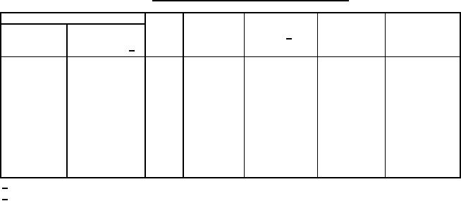
TABLE I. Type designation and switching characteristics.
Type designation
Maximum
Dimension
Approximate
Number of
rotational
"X" 2/
Style
weight
Rotor
sections
torque
Component
.062 (1.57)
(ounces)
designation 1/
(inch-pounds)
S
1
JF
4
1.960 (49.78)
4.2
8
S
1
JF
5
2.250 (57.15)
4.4
8
S
2
JF
1
1.090 (27.69)
3.5
5
S
2
JF
2
1.380 (35.05)
3.7
5
S
2
JF
3
1.670 (42.42)
3.9
5
S
2
JF
4
1.960 (49.78)
4.2
8
S
2
JF
5
2.250 (57.15)
4.4
8
S
2
JFM
3
1.950 (49.53)
4.4
5
S
2
JFM
4
2.240 (56.90)
4.6
8
S
2
JFM
5
2.530 (64.26)
4.9
8
1/ For rotor designation, see figure 2.
2/ Dimensions are in inches. Metric equivalents (to the nearest 0.01 mm) are given for general information only
and are based upon 1 inch = 25.4 mm.
4