MIL-DTL-15291/5B
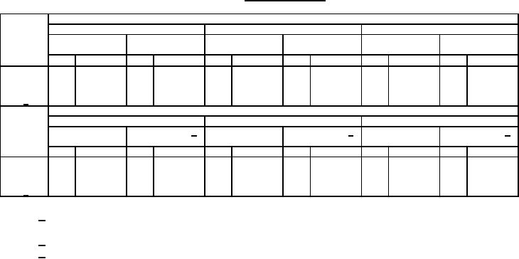
TABLE III. Extended ratings.
AC - 60 or 400 Hertz
Switching
125 volts
250 volts
500 volts
character-
Resistive or
Inductive load
Resistive or
Inductive load
Resistive or
Inductive load
istics
lamp load
0.75 pF
lamp load
0.75 pF
lamp load
0.75 pF
Amp Operations Amp Operations
Amp Operations Amp Operations
Amp Operations Amp Operations
All
30
20,000
30
20,000
30
20,000
30
20,000
30
20,000
30
20,000
E, F
40
6,000
40
6,000
---
---
---
---
---
---
---
---
A, B 1/
40
6,000
40
6,000
30
6,000
30
6,000
30
6,000
30
6,000
DC
120 volts
250 volts
350 volts
Resistive or
Inductive, load 4/
Resistive or
Inductive, load 4/
Resistive or
Inductive, load 4/
lamp load
lamp load
lamp load
Amp Operations Amp Operations
Amp Operations Amp Operations
Amp Operations Amp Operations
All
30
13,000
25
6,000
15
13,000
---
---
---
---
---
---
A, B
30
15,000
25
6,000
25
6,000
25
6,000
15
6,000
15
6,000
A, B 3/
---
---
---
---
30
15,000
---
---
---
---
---
---
1/ Single pole break - all other ratings are based on breaking both sides of the line in accordance
with figures 1 and 2 of MIL-DTL-15291.
2/ 0.08 henry for inductive current.
3/ Switch with special arc snuffers.
Sealed mounting: Switches listed in table I as having "Y" dimensions not less than 7/16 inch can be
mounted with a kit, figure 5, to effect a submersible seal (SBM 15) between switch and mounting panel.
Panel drilling must comply with figure 6. Kits not supplied unless specified (see 6.2 of MIL-DTL-15291).
7
For Parts Inquires call Parts Hangar, Inc (727) 493-0744
© Copyright 2015 Integrated Publishing, Inc.
A Service Disabled Veteran Owned Small Business