A-A-52482B
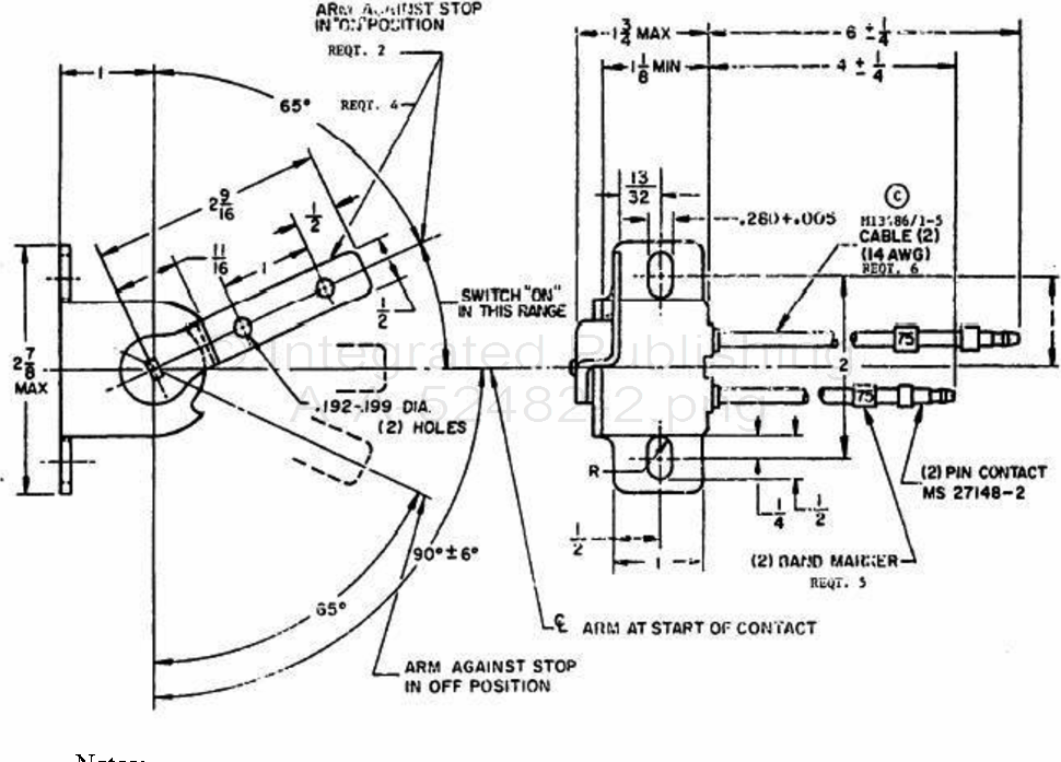
2.2 Design and construction. Unless otherwise specified in figure 1, the design and configuration of the switch shall be in accordance with the manufacturer's drawings.

Notes:
1. Dimensions are in inches, unless otherwise specified, tolerances are ± 1/32 on fractions, ± .005 on decimals, ± 2° on angles.
Figure 1. Design and configuration.
2.3 Performance. The switch shall perform as specified here-in when energized at a rated load of 28 Vdc.
2.3.1 Voltage drop.
2.3.2 Overload. To determine the overload, the switch shall be energized by a 28 Vdc source and connected to loads 40 percent greater than rated (lamp, resistive) loads. The switch shall be operated for 100 cycles at each specified load. For lamp loads, the load cycle shall be 1 ±0.1 second "on" and 5 ±0.1 seconds "off" (10 cycles per minute). After cycle is completed, the switch shall meet the requirements of 2.3.1.
For Parts Inquires call Parts Hangar, Inc (727) 493-0744
© Copyright 2015 Integrated Publishing, Inc.
A Service Disabled Veteran Owned Small Business